


Midi Generator with ATtiny26-8PI
#ATtiny26
#MIDI
#AVR
#microcontroller
#tone generator
#LED indicator
#key input
#music electronics
#digital sound

Description: This circuit based on ATtiny26 but it could be anyone microcontroller of AVR family. Produce stable one MIDI tone and you can change it by press some keys like to change midi channel 0-15, velocity 0-127, pitch 0-127. It is start from center tone (C) at channel 0 with velocity 30. Every tone is equivalence with two midi events "note on" and "note off". A LED is used to show the start and stop of the midi tone. This LED is turn-on every time a command is executed by the key pressing.
The described circuit employs an ATtiny26 microcontroller, which is part of the AVR family, to generate a stable MIDI tone. The design allows for user interaction through key presses, enabling the modification of MIDI parameters such as channel (0-15), velocity (0-127), and pitch (0-127). The circuit initializes with a central tone of C at MIDI channel 0 and a velocity setting of 30, ensuring a consistent starting point for sound generation.
The MIDI tone generation is achieved through a combination of digital signal processing techniques implemented within the microcontroller. Each tone corresponds to two MIDI events: "note on" and "note off". This dual-event system is essential for creating a realistic musical experience, as it allows for the control of note duration and articulation.
Key presses are detected using a matrix keypad or individual push buttons connected to the microcontroller's input pins. The microcontroller processes these inputs to alter the MIDI parameters accordingly. For instance, pressing a specific key can increment or decrement the MIDI channel, adjust the velocity, or change the pitch of the generated tone.
An LED indicator is incorporated into the design to provide visual feedback to the user. This LED illuminates whenever a command is executed via key presses, signaling the initiation or termination of the MIDI tone. The LED's state is controlled by the microcontroller, which toggles it on during the "note on" event and turns it off during the "note off" event.
To facilitate the MIDI communication, the circuit includes a MIDI output interface that adheres to the standard MIDI protocol. This typically involves a 5-pin DIN connector through which the MIDI messages are transmitted to external devices such as synthesizers or MIDI controllers.
The overall design emphasizes simplicity and functionality, making it suitable for various applications in electronic music production and performance. The use of the ATtiny26 allows for a compact and efficient circuit, while the flexibility in MIDI parameter adjustments enhances the user experience.This circuit based on ATtiny26 but it could be anyone microcontroller of AVR family. Produce stable one MIDI tone and you can change it by press some keys like to change midi channel 0-15 , velocity 0-127, pitch 0-127. It is start from center tone (C) at channel 0 with velocity 30. Every tone is equivalence with two midi events "note on" and "note off". A LED is used to show the start and stop of the midi tone. This LED is turn-on every time a command is executed by the key pressing.
The described circuit employs an ATtiny26 microcontroller, which is part of the AVR family, to generate a stable MIDI tone. The design allows for user interaction through key presses, enabling the modification of MIDI parameters such as channel (0-15), velocity (0-127), and pitch (0-127). The circuit initializes with a central tone of C at MIDI channel 0 and a velocity setting of 30, ensuring a consistent starting point for sound generation.
The MIDI tone generation is achieved through a combination of digital signal processing techniques implemented within the microcontroller. Each tone corresponds to two MIDI events: "note on" and "note off". This dual-event system is essential for creating a realistic musical experience, as it allows for the control of note duration and articulation.
Key presses are detected using a matrix keypad or individual push buttons connected to the microcontroller's input pins. The microcontroller processes these inputs to alter the MIDI parameters accordingly. For instance, pressing a specific key can increment or decrement the MIDI channel, adjust the velocity, or change the pitch of the generated tone.
An LED indicator is incorporated into the design to provide visual feedback to the user. This LED illuminates whenever a command is executed via key presses, signaling the initiation or termination of the MIDI tone. The LED's state is controlled by the microcontroller, which toggles it on during the "note on" event and turns it off during the "note off" event.
To facilitate the MIDI communication, the circuit includes a MIDI output interface that adheres to the standard MIDI protocol. This typically involves a 5-pin DIN connector through which the MIDI messages are transmitted to external devices such as synthesizers or MIDI controllers.
The overall design emphasizes simplicity and functionality, making it suitable for various applications in electronic music production and performance. The use of the ATtiny26 allows for a compact and efficient circuit, while the flexibility in MIDI parameter adjustments enhances the user experience.This circuit based on ATtiny26 but it could be anyone microcontroller of AVR family. Produce stable one MIDI tone and you can change it by press some keys like to change midi channel 0-15 , velocity 0-127, pitch 0-127. It is start from center tone (C) at channel 0 with velocity 30. Every tone is equivalence with two midi events "note on" and "note off". A LED is used to show the start and stop of the midi tone. This LED is turn-on every time a command is executed by the key pressing.
GVI Digital Remote Control
The GVI Digital Remote Control for DSLR cameras represents an advancement over previous remote controls for the Canon EOS 450D. This remote utilizes the AVR Microcontroller ATmega328 and is programmed using the Arduino IDE. It serves as a tool for...

pc based digital ic tester
Check the following ICs: 7400, 7402, 7404, 7408, 7432, 7486. A Visual Basic program is utilized to display the results on the PC. The microcontroller AT89S52 receives the IC number from the PC, verifies the logic gates with the truth...
clap sensor construction
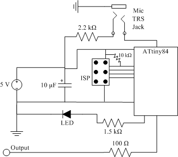
The clap sensor is a straightforward circuit that consists of a PC microphone, a microcontroller, and an output. The circuit design features the ATtiny84 microcontroller, chosen for familiarity with the AVR architecture and accessibility to necessary tools. The ATtiny84 is...

POWER LINE MODEM FOR COMPUTER CONTROL
This circuit employs an 87C57 microcontroller along with several peripherals to convert X-10 power-line carrier-code formats from a personal computer for use with an X-10 power-line interface in a home-control system. Software details can be found in the reference.
The circuit...

thermometer dengan avr
The module provides a pre-wired multiplex of a 4-digit common anode LED, which is quite useful. The soldering pad for these signals is shown in the first picture below. A friend provided an AT90S2313 chip, along with a simple homemade...

MIDI Drum Machine Schematic Main CPU Section
The 82C55 and seven-segment decoders on the display board will be replaced with a set of shift registers to eliminate the need for the 82C55 and the extensive wiring. The ADC0804 will be substituted with a serial interface ADC chip,...

MIDI tester circuit
Sometimes when experimenting with different soundcards and MIDI interfaces it is useful to see if there is some data going in MIDI interface. This can be easily tested with this adapter, which converts the midi signals to visible light pulses....

Preprogrammed single-chip microcontroller
Twenty-five musical keys and 25 LEDs are provided to denote F to F" with half notes in between. Memory can store a played tune. There are ten preprogrammed tunes (each has an average of 55 notes) masked in the chip....

MIDI Sync Box
All components function correctly. The final software comprises 930 lines of assembler code. ProTel was utilized to create the final circuit diagram. The design has been streamlined to a single chip, with the PIC microcontroller performing all tasks. It directly...