


pic 16f887 based digital thermometer
#PIC16F887
#digital thermometer
#DS1820
#1-Wire bus
#temperature sensor
#microcontroller
#embedded systems
#sensor interface
#hardware configuration
#communication protocol
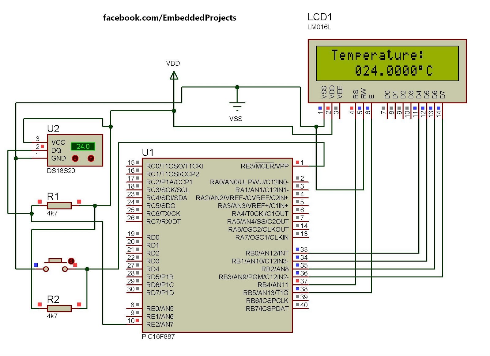
Description: The hardware configuration for utilizing multiple 1-Wire temperature sensors, such as the DS1820, is straightforward. Communication between the microcontroller and the temperature sensors occurs over a single-wire bus. Additionally, it is possible to power the devices directly through this 1-Wire bus. An almost unlimited number of 1-Wire devices can be connected to the bus since each device possesses a unique 64-bit ROM code identifier that allows for individual addressing. Temperature measurement is a common function performed by the microcontroller, and the DS1820 sensor is employed for this purpose. It can measure temperatures ranging from -55 °C to 125 °C with an accuracy of 0.5 °C. Data transfer to the microcontroller utilizes a specialized serial communication method known as 1-Wire. Given the widespread use of these sensors, the commands necessary for operation are encapsulated in functions within the One_Wire library. There are three functions available, allowing users to implement the sensor without the need for extensive documentation from the manufacturer; copying the relevant functions into the program suffices.
The circuit configuration for the DS1820 temperature sensor within a 1-Wire network is designed for simplicity and efficiency. The microcontroller serves as the central unit, managing communication and data collection from multiple DS1820 sensors connected to a single 1-Wire bus. Each DS1820 sensor is uniquely identified by its 64-bit ROM code, enabling the microcontroller to address each sensor individually, even when multiple sensors are connected in parallel.
In this configuration, the 1-Wire bus not only facilitates data communication but also provides power to the sensors, which allows for a reduction in wiring complexity. The bus operates on a master/slave architecture, where the microcontroller acts as the master device, sending commands and receiving data from the slave sensors. The 1-Wire protocol is efficient, requiring only a single data line for bi-directional communication, thus minimizing the number of pins required on the microcontroller.
The DS1820 sensor is capable of measuring a wide temperature range, making it suitable for various applications, from environmental monitoring to industrial temperature control. The sensor's accuracy of 0.5 °C ensures reliable readings for most applications. The One_Wire library, which contains predefined functions for interacting with the DS1820, simplifies the programming process, allowing users to easily implement temperature measurement without delving into complex protocol details.
In practice, the implementation involves initializing the One_Wire library, addressing each sensor using its unique ROM code, and executing commands to read temperature data. The microcontroller processes this data for further applications, such as logging, display, or control functions. Overall, the integration of multiple DS1820 sensors in a 1-Wire configuration represents an effective solution for temperature measurement in a variety of electronic projects.The hardware configuration when using multiple 1-Wire temperature sensors like the DS1820 is very simple, as illustrated in the block diagram below. A single-wire bus is used for communication between the microcontroller and the temperature sensor. It is also possible to power the devices direclty via this 1-Wire bus. An almost unlimited number of 1-WireTM devices can be connected to the bus because each device has a unique 64-bit ROM code identifier which is used to address each sensor. Temperature measurement is one of the most common tasks performed by the microcontroller. A DS1820 sensor is used for measurement here. It is capable of measuring temperature in the range of -55 °C to 125 °C with 0. 5 °C accuracy. For the purpose of transferring data to the microcontroller, a special type of serial communication called 1-wire is used.
Due to a simple and wide use of these sensors, commands used to run and control them are in the form of functions stored in the One_Wire library. There are three functions in total: Concretely, you don`t have to study documentation provided by the manufacturer in order to use this sensor.
It is sufficient to copy some of these functions in the program.
The circuit configuration for the DS1820 temperature sensor within a 1-Wire network is designed for simplicity and efficiency. The microcontroller serves as the central unit, managing communication and data collection from multiple DS1820 sensors connected to a single 1-Wire bus. Each DS1820 sensor is uniquely identified by its 64-bit ROM code, enabling the microcontroller to address each sensor individually, even when multiple sensors are connected in parallel.
In this configuration, the 1-Wire bus not only facilitates data communication but also provides power to the sensors, which allows for a reduction in wiring complexity. The bus operates on a master/slave architecture, where the microcontroller acts as the master device, sending commands and receiving data from the slave sensors. The 1-Wire protocol is efficient, requiring only a single data line for bi-directional communication, thus minimizing the number of pins required on the microcontroller.
The DS1820 sensor is capable of measuring a wide temperature range, making it suitable for various applications, from environmental monitoring to industrial temperature control. The sensor's accuracy of 0.5 °C ensures reliable readings for most applications. The One_Wire library, which contains predefined functions for interacting with the DS1820, simplifies the programming process, allowing users to easily implement temperature measurement without delving into complex protocol details.
In practice, the implementation involves initializing the One_Wire library, addressing each sensor using its unique ROM code, and executing commands to read temperature data. The microcontroller processes this data for further applications, such as logging, display, or control functions. Overall, the integration of multiple DS1820 sensors in a 1-Wire configuration represents an effective solution for temperature measurement in a variety of electronic projects.The hardware configuration when using multiple 1-Wire temperature sensors like the DS1820 is very simple, as illustrated in the block diagram below. A single-wire bus is used for communication between the microcontroller and the temperature sensor. It is also possible to power the devices direclty via this 1-Wire bus. An almost unlimited number of 1-WireTM devices can be connected to the bus because each device has a unique 64-bit ROM code identifier which is used to address each sensor. Temperature measurement is one of the most common tasks performed by the microcontroller. A DS1820 sensor is used for measurement here. It is capable of measuring temperature in the range of -55 °C to 125 °C with 0. 5 °C accuracy. For the purpose of transferring data to the microcontroller, a special type of serial communication called 1-wire is used.
Due to a simple and wide use of these sensors, commands used to run and control them are in the form of functions stored in the One_Wire library. There are three functions in total: Concretely, you don`t have to study documentation provided by the manufacturer in order to use this sensor.
It is sufficient to copy some of these functions in the program.
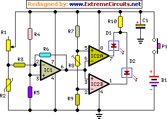
Energy Leak Detector
This sensitive circuit functions primarily as a comparator, capable of detecting minimal temperature changes relative to ambient temperature. It was originally designed to identify drafts around doors and windows that lead to energy loss, but it can be utilized in...

MCU controlled Bluetooth automation
The microcontroller used is 0822 zilog encore! 8k series (soic,28pin) as shown on the figure. Is a programmable microcontroller, the functions used are the GPIO and the UART of the chip. GPIO is used on led indicators, and the UART...
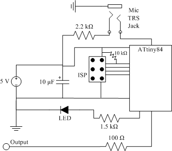
clap sensor construction
The clap sensor is a straightforward circuit that consists of a PC microphone, a microcontroller, and an output. The circuit design features the ATtiny84 microcontroller, chosen for familiarity with the AVR architecture and accessibility to necessary tools. The ATtiny84 is...

Handy Cricket Hardware Description
This document presents an overview of the hardware design of the Handy Cricket.
The Handy Cricket is a compact electronic device designed for educational and recreational purposes, primarily aimed at children. The hardware design incorporates various components that work together to...

Digital Remote Thermometer Circuit With Receiver and Transmitter
This circuit is designed for precise centigrade temperature measurement. It features a transmitter section that converts the sensor's output voltage, which is proportional to the measured temperature, into frequency. The output frequency bursts are transmitted through the mains supply cables....

temp control circuit
For various experiments, such as solar air heaters, an automatic fan activation and deactivation system is required. A straightforward solution is to use a bimetal snap disc thermal sensor. This sensor functions as a switch that closes when a specific...

Buffering TMP01 Temperature Sensor
This is a buffer circuit for the TMP01 temperature sensor. The output of this sensor is a low impedance DC output voltage with a 5 mV/K temperature coefficient.
The buffer circuit designed for the TMP01 temperature sensor serves to isolate the...
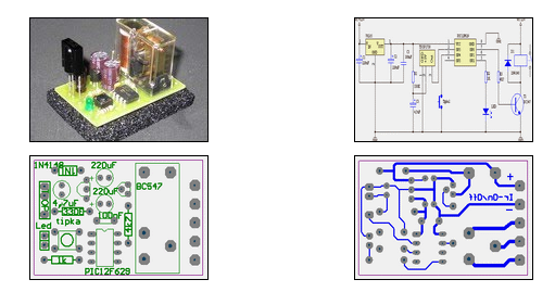
IR On/Off Switch Using Microcontroller
The ability to turn electrical devices ON or OFF using a remote control is a well-established concept, with numerous devices effectively performing this function.
To implement a remote control system for switching electrical devices, a typical schematic would include several key...

led blinking program with pic16f887
The code in mikroC PRO for the PIC16F887 microcontroller is designed to operate with an 8.000 MHz clock frequency on a Microchip 44-pin demo board. The routines have been developed using HITECH C, but the focus is on utilizing mikroC...