


pic programmer using pic16f83
#PIC16F83
#PIC16C84
#PIC16F84
#programmer
#parallel port
#microcontroller
#PC interface
#embedded systems
#DIY electronics

NOPPP is a straightforward programmer designed for the PIC16C84, PIC16F83, and PIC16F84(A) microcontrollers. It connects to the parallel port of a PC. Plans for this device were published in a magazine.
The NOPPP programmer is an essential tool for developers working with the specified PIC microcontrollers, providing a cost-effective solution for programming and debugging. The device utilizes the parallel port interface, which allows for direct communication between the programmer and the PC, facilitating the transfer of program data to the microcontroller.
The circuit design typically includes a series of resistors, capacitors, and transistors to interface the parallel port signals with the microcontroller's programming pins. The programmer operates by sending specific voltage levels and pulse sequences that correspond to the programming commands required by the microcontrollers.
Key components in the schematic may include a 74HC14 hex inverter, which can be used to condition the signals from the parallel port, ensuring that they meet the required logic levels for the microcontroller. Additionally, a set of diodes may be incorporated to protect against reverse polarity and to ensure that the voltage levels do not exceed the maximum ratings of the microcontroller.
The programmer is designed to be powered directly from the parallel port, eliminating the need for an external power supply. This feature enhances portability and ease of use, making it suitable for both hobbyists and professionals.
Overall, the NOPPP programmer represents a valuable resource for anyone working with PIC16C84, PIC16F83, and PIC16F84(A) microcontrollers, providing an accessible means to program and test applications efficiently.NOPPP is a simple programmer for PIC16C84, PIC16F83, and PIC16F84(A) microcontrollers. It attaches to the parallel port of a PC. Plans were published in El..
The NOPPP programmer is an essential tool for developers working with the specified PIC microcontrollers, providing a cost-effective solution for programming and debugging. The device utilizes the parallel port interface, which allows for direct communication between the programmer and the PC, facilitating the transfer of program data to the microcontroller.
The circuit design typically includes a series of resistors, capacitors, and transistors to interface the parallel port signals with the microcontroller's programming pins. The programmer operates by sending specific voltage levels and pulse sequences that correspond to the programming commands required by the microcontrollers.
Key components in the schematic may include a 74HC14 hex inverter, which can be used to condition the signals from the parallel port, ensuring that they meet the required logic levels for the microcontroller. Additionally, a set of diodes may be incorporated to protect against reverse polarity and to ensure that the voltage levels do not exceed the maximum ratings of the microcontroller.
The programmer is designed to be powered directly from the parallel port, eliminating the need for an external power supply. This feature enhances portability and ease of use, making it suitable for both hobbyists and professionals.
Overall, the NOPPP programmer represents a valuable resource for anyone working with PIC16C84, PIC16F83, and PIC16F84(A) microcontrollers, providing an accessible means to program and test applications efficiently.NOPPP is a simple programmer for PIC16C84, PIC16F83, and PIC16F84(A) microcontrollers. It attaches to the parallel port of a PC. Plans were published in El..

GDS Chip Programmer
Generic Digital Switches are in-circuit programmable devices made by Lattice Semiconductor that allow pin to pin routing, buffering, and inversion. Perfect for making last minute circuit changes.
Generic Digital Switches are versatile components utilized in electronic circuits for their ability to...

using microcontrollers
This schematic illustrates the placement of a decoupling capacitor on the right side, which should be positioned as close as possible to the power pins of the microcontroller. It includes a crystal oscillator, which is optional; an internal RC oscillator...

microcontroller How does this power supply circuit work? (MCU + LM317)
The filter consisting of resistors R1, R2, and capacitor C1 integrates the PWM waveform. The purpose of the operational amplifier appears to be that of a non-inverting amplifier, with the gain determined by resistors R6 and R7. However, the need...

Power supplies for microcontroller based projects
This document discusses the use of small microcontrollers, such as those from the PIC and Atmel series, which typically operate at 5V and require less than 100mA for complete system functionality. Some PICs can function at lower voltages, such as...
Multitasking Pins circuit
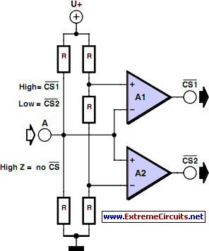
It is entirely logical that low-cost miniature microcontrollers have fewer pins than their larger counterparts, sometimes too few. Consideration has been given to how to economize on pins by making them perform the work of several. It was noted that...

Microcontroller interfacing with RS 232
Standard serial interfacing of a microcontroller (TTL) with a PC or any RS232C standard device requires a TTL to RS232 level converter. A MAX232 is used for this purpose. It provides a 2-channel RS232C port and requires external 10µF capacitors.
The...
Pic Circuits
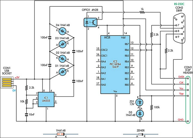
A small biped walker constructed from 2mm plywood, powered by two RC servos. It utilizes the widely available and programmable flash microcontroller PIC16F84. This simple circuit is designed to program the PIC16F84 and similar flash memory components. The project includes...

delay
This article outlines the construction of a simple microcontroller-based delay circuit designed for photographic applications, such as drop or high-speed photography. It is capable of controlling the trigger lag for cameras and flash units, generating periodic trigger pulses, or managing...

PIC controlled DDS VFO
This is a 0 - 6 MHz DDS VFO controlled by a PIC16F84 (or C84). The VFO is separated into two modules, the DDS module and the controller module. The PCB layout (double sided) for the DDS module is included...