


PIC16F886 Based Horn Driver ECE Mini Project
#PIC16F886
#horn driver
#Microchip
#microcontroller
#peripheral resources
#ECE project
#simple circuit
#external components

Description: A horn driver project developed by Microchip Technology is illustrated in this circuit diagram. This horn driver project utilizes the PIC16F886 microcontroller from Microchip. The circuit diagram for the PIC microcontroller horn driver is straightforward and requires minimal external components. The PIC MCU is equipped with peripheral resources that enable it to provide horn driver functionalities efficiently. Among these peripherals is the Enhanced Capture/Compare/PWM (ECCP) module, which operates in Pulse-Width Modulation (PWM) Half-Bridge mode to control the two horn drive leads. Additionally, it features a single ADC input to monitor the feedback from the horn after it has been conditioned. Understanding the horn characteristics is essential for determining the parameters for the PWM module's range. For instance, if the horn has a resonant frequency of 3.5 kHz ± 0.5 kHz, the PWM module is designed to output a PWM frequency ranging from 3 kHz to 4 kHz with a 50% duty cycle. When the device operates on an internal oscillator at 8 MHz, Timer2, which drives the PWM period, generates 2 million clocks per second. For a 3 kHz period, this equates to 667 clocks per cycle, while a 4 kHz period corresponds to 500 clocks per cycle. Since Timer2 is an 8-bit timer with a maximum value of 255, the clocks per cycle must be divided using a prescaler of 4, resulting in 166 clocks per cycle for 3 kHz and 125 clocks per cycle for 4 kHz. The PWM output, driven by the ECCP module in Half-Bridge mode, activates both P1A and P1B outputs as high. It will cycle through the 125 to 166 clocks per cycle periods at a defined rate, and as the Period register is populated, the value is halved and loaded into the Duty Cycle register for a 50% duty cycle. This configuration establishes the new PWM period for evaluating feedback from the horn driver and drives the transistor to elevate the voltage seen at the horn lead to 9V.
The horn driver circuit based on the PIC16F886 microcontroller is designed for efficient control of horn actuators through precise PWM signal generation. The ECCP module's Half-Bridge mode is particularly effective for driving inductive loads such as horns, allowing for effective control of the voltage and current supplied to the horn. The integration of an ADC input enables real-time monitoring of the horn's performance, facilitating feedback control mechanisms that can adjust the PWM parameters based on the horn's response.
The circuit's design emphasizes simplicity, requiring only essential external components, which enhances reliability and reduces overall system complexity. The use of the internal 8 MHz oscillator simplifies the design by eliminating the need for an external clock source, while the Timer2 functionality allows for accurate timing control necessary for PWM signal generation.
The prescaling mechanism ensures that the PWM frequency remains within the operational limits of the Timer2, providing a range of output frequencies suitable for various horn types. The ability to adjust the duty cycle to 50% ensures that the horn receives adequate power for optimal performance without overheating or damaging the components. This project exemplifies an effective application of microcontroller technology in automotive or industrial horn activation systems, showcasing the capabilities of the PIC16F886 in real-world applications.A very interesting horn driver project presented by Microchip technology is presented in this circuit diagram. This horn driver project is based on PIC16F886 microcontroller, from Microchip. This microcontroller horn driver circuit diagram is very simple and require few external components. The PIC MCU has peripheral resources within the devic e to provide horn driver services in a very simple manner. The PIC MCU peripherals include the Enhanced CCP (ECCP) module in Pulse-Width Modulation (PWM) Half-Bridge mode to drive the 2 horn drive leads and a single ADC input to monitor the horn feedback after it has been conditioned. Horn characteristics are required to determine the defined parameters for the range of the PWM module.
For example, a horn with a resonant frequency of 3. 5 kHz ± 0. 5 kHz; the PWM module generates a PWM frequency output from 3 kHz to 4 kHz with 50% duty cycle. With a device that is running off of the internal oscillator at 8 MHz, the clock source to Timer2 that drives the PWM period generates 2M clocks per second. For a 3 kHz period, this is 667 clocks per cycle, and for a 4 kHz period, this is 500 clocks per cycle.
Because Timer2 is an 8-bit timer, accepting only a maximum value of 255, these clocks per cycle must be divided (a prescaler of divide-by-4, yielding 166 clocks per cycle for 3 kHz, and 125 clocks per cycle for 4 kHz). The PWM output driven by the ECCP module in Half-Bridge mode, with both the P1A and P1B outputs active-high, will step through the 125 through 166 clocks per cycle periods at a period rate, and as the Period register is loaded, the value will be dividedby- 2 and loaded into the Duty Cycle register for a 50% duty cycle.
This will become the new PWM period for measuring the feedback from the horn driver, and drives the transistor that raises the level that the horn lead sees, to 9V.
The horn driver circuit based on the PIC16F886 microcontroller is designed for efficient control of horn actuators through precise PWM signal generation. The ECCP module's Half-Bridge mode is particularly effective for driving inductive loads such as horns, allowing for effective control of the voltage and current supplied to the horn. The integration of an ADC input enables real-time monitoring of the horn's performance, facilitating feedback control mechanisms that can adjust the PWM parameters based on the horn's response.
The circuit's design emphasizes simplicity, requiring only essential external components, which enhances reliability and reduces overall system complexity. The use of the internal 8 MHz oscillator simplifies the design by eliminating the need for an external clock source, while the Timer2 functionality allows for accurate timing control necessary for PWM signal generation.
The prescaling mechanism ensures that the PWM frequency remains within the operational limits of the Timer2, providing a range of output frequencies suitable for various horn types. The ability to adjust the duty cycle to 50% ensures that the horn receives adequate power for optimal performance without overheating or damaging the components. This project exemplifies an effective application of microcontroller technology in automotive or industrial horn activation systems, showcasing the capabilities of the PIC16F886 in real-world applications.A very interesting horn driver project presented by Microchip technology is presented in this circuit diagram. This horn driver project is based on PIC16F886 microcontroller, from Microchip. This microcontroller horn driver circuit diagram is very simple and require few external components. The PIC MCU has peripheral resources within the devic e to provide horn driver services in a very simple manner. The PIC MCU peripherals include the Enhanced CCP (ECCP) module in Pulse-Width Modulation (PWM) Half-Bridge mode to drive the 2 horn drive leads and a single ADC input to monitor the horn feedback after it has been conditioned. Horn characteristics are required to determine the defined parameters for the range of the PWM module.
For example, a horn with a resonant frequency of 3. 5 kHz ± 0. 5 kHz; the PWM module generates a PWM frequency output from 3 kHz to 4 kHz with 50% duty cycle. With a device that is running off of the internal oscillator at 8 MHz, the clock source to Timer2 that drives the PWM period generates 2M clocks per second. For a 3 kHz period, this is 667 clocks per cycle, and for a 4 kHz period, this is 500 clocks per cycle.
Because Timer2 is an 8-bit timer, accepting only a maximum value of 255, these clocks per cycle must be divided (a prescaler of divide-by-4, yielding 166 clocks per cycle for 3 kHz, and 125 clocks per cycle for 4 kHz). The PWM output driven by the ECCP module in Half-Bridge mode, with both the P1A and P1B outputs active-high, will step through the 125 through 166 clocks per cycle periods at a period rate, and as the Period register is loaded, the value will be dividedby- 2 and loaded into the Duty Cycle register for a 50% duty cycle.
This will become the new PWM period for measuring the feedback from the horn driver, and drives the transistor that raises the level that the horn lead sees, to 9V.

delay circuit for photography
This article outlines the construction of a simple microcontroller-based delay circuit designed for photographic applications such as drop or high-speed photography. It can control the trigger lag of cameras and flash units, generate periodic trigger pulses, or manage magnetic valves....

repair microcontroller circuit
The difference between these two ICs. A microcontroller is a specialized type of microprocessor designed to be self-sufficient and cost-effective, while a microprocessor is typically intended for general-purpose use, such as in personal computers (PCs). The microcontroller integrates several useful...

Exploring Microcontrollers
Many of today's appliances feature displays and buttons. Instead of relying on motors and gears, numerous household items now incorporate embedded microcontrollers. This exploration focuses on how to experiment with microcontrollers at home.
Microcontrollers serve as the central processing units for...

Experimental I/O board for microcontrollers
For beginners experiencing similar challenges, a general-purpose I/O board is recommended to minimize prototyping time and maximize space on the breadboard for projects. The construction of this board is straightforward. Basic I/O devices can be soldered onto a general-purpose perforated...

integrated circuit Improving absolute precision of ADC to balance battery voltage
Utilize a high-performance microcontroller (Piccolo TMS320F28035, 12-bit resolution, +/- 4 LSB offset, +/- 60 LSB gain) to measure the voltage across stacked battery cells and control related analog electronics for charge equalization. The microcontroller will also save data in EEPROM...
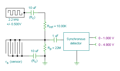
measurement conductance cell constant
A small transmitter board interfaces with a microcontroller and conductivity probe to measure liquid conductance and conductivity. Precise equations and measurements are provided for this microcontroller-controlled conductivity meter.
The described circuit consists of a compact transmitter board that serves as an...

How to Design Battery Charger Applications that Require External Microcontrollers and Related System-Level Issues
Application note on designing linear and switch-mode (switching DC-DC converter current source) battery charger applications that require external microcontrollers and related system-level issues for notebook computers.
The application note provides guidance on the design of both linear and switching DC-DC converter...

Controlling high-current circuits
Digital output from a microcontroller is typically a low-amperage signal. For example, when a pin is set HIGH on the microcontroller (in Wiring/Arduino, it is digitalWrite(somePin, HIGH);), the voltage from that pin is usually +3.3V or +5V, with the current...

Low Resource Microcontroller 3 Phase BLDC Motor Speed Controller
This article discusses a minimal resource microcontroller implementation for a three-phase Brushless DC (BLDC) motor, focusing on a closed-loop speed motor controller application based on a Microchip PIC12 device. It demonstrates how minimization techniques can reduce the number of I/O...