


PIC18F2550 Pinguino
#PIC18F2550
#Pinguino
#bootloader
#USB power
#external power supply
#microcontroller
#programming
#reset switch

Description: This board features a reset switch. When the reset switch is pressed, the board enters bootloader mode, waiting for an upload from the development computer for a duration of 5 seconds. After this period, the currently loaded program is executed. The board can be powered through a USB connector, subject to the power limitations of the connected computer. Additionally, it can be powered by an external power supply ranging from 4.2V to 5.5V. An onboard regulator can be added to provide a stable 5V Vcc for the microcontroller chip, such as using a 7805 voltage regulator.
The board is utilized for programming the Pinguino bootloader onto a new chip. It includes various definitions for pin connections such as PGC, PGD, VPP, VCC, and redled, which correspond to specific pins on the microcontroller. The firmware includes arrays for bulk erase and write commands, as well as functions to manage the programming process, including starting and stopping programming mode, sending commands to the chip, and reading flash memory.
The setup function initializes the necessary pins for operation, while the loop function contains the logic for erasing the chip and programming it with new data.
The board's functionality is centered around its ability to program microcontrollers using the Pinguino bootloader, making it a versatile tool for electronics development and prototyping.
The board's reset switch serves as a critical interface for entering bootloader mode, allowing developers to upload new firmware to the microcontroller. The USB power supply option provides convenience for development environments, while the external power supply capability ensures flexibility in various applications.
The addition of a voltage regulator simplifies the power management for the microcontroller, ensuring it operates within its specified voltage range. The programming interface is designed to facilitate easy communication with the microcontroller, utilizing defined pins for command and data transfer.
The programming process is managed by a series of well-defined functions that handle the intricacies of microcontroller programming, including chip erase and data writing. The use of arrays for command sequences enhances modularity and ease of updates to the firmware.
Overall, the board's design emphasizes ease of use, flexibility in power options, and a streamlined programming process, making it an effective tool for developers working with microcontroller applications.There is one switch to reset the board. When reset is held, the board is in bootloader mode waiting for an upload from the development computer for 5 seconds. After 5 seconds, the current program is run. This board can be powered by the USB connector subject to computer power limitations. It can be powered by an external power supply from 4. 2Vcc t o 5. 5Vcc. You can add an onboard regulator to provide 5V Vcc for the microcontroller chip (using a 7805 voltage regulator for example). // This is a tool to program the pinguino bootloader in a new chip // with your Pinguino, the self replicating machine!
// Jean-Pierre MANDON 2010 // Fixed bug 02/07/2011 PGM pin is no longer used #define PGC 1 // connected to the PGC pin of the blank chip #define PGD 2 // connected to the PGD pin of the blank chip #define VPP 3 // connected to the VPP pin of the blank chip #define VCC 6 // connected to the power on transistor #define redled 5 uchar bulkerase[48] ={0x00, 0x3C, 0x0E, 0x00, 0xF8, 0x6E, 0x00, 0x00, 0x0E, 0x00, 0xF7, 0x6E, 0x00, 0x05, 0x0E, 0x00, 0xF6, 0x6E, 0x0C, 0x3F, 0x3F, 0x00, 0x3C, 0x0E, 0x00, 0xF8, 0x6E, 0x00, 0x00, 0x0E, 0x00, 0xF7, 0x6E, 0x00, 0x04, 0x0E, 0x00, 0xF6, 0x6E, 0x0C, 0x8F, 0x8F, 0x00, 0x00, 0x00, 0x00, 0x00, 0x00}; uchar startwrite[24]={0x00, 0xA6, 0x8E, 0x00, 0xA6, 0x9C, 0x00, 0x00, 0x0E, 0x00, 0xF8, 0x6E, 0x00, 0x00, 0x0E, 0x00, 0xF7, 0x6E, 0x00, 0x00, 0x0E, 0x00, 0xF6, 0x6E}; uchar startwrid[24] ={0x00, 0xA6, 0x8E, 0x00, 0xA6, 0x8C, 0x00, 0x30, 0x0E, 0x00, 0xF8, 0x6E, 0x00, 0x00, 0x0E, 0x00, 0xF7, 0x6E, 0x00, 0x00, 0x0E, 0x00, 0xF6, 0x6E}; uchar checkmem[32]; uint address=0; #define pic_on() digitalWrite(VCC, LOW) #define pic_off() digitalWrite(VCC, HIGH) // begin programming mode // power is on ( VCC and Programing voltage ) void start_pgm() { digitalWrite(VPP, HIGH); delayMicroseconds(4); } // end programming mode // power is on ( VCC and Programing voltage ) void stop_pgm() { digitalWrite(PGD, LOW); digitalWrite(PGC, LOW); digitalWrite(VPP, LOW); } // send a command to the chip // SPI soft void send_command(uchar command, uchar lowbyte, uchar highbyte) { unsigned char i; for (i=0;i<4;i+) { digitalWrite(PGC, HIGH); if (command&1)=1) digitalWrite(PGD, HIGH); else digitalWrite(PGD, LOW); digitalWrite(PGC, LOW); command=command>>1; } for (i=0;i<8;i+) { digitalWrite(PGC, HIGH); if (lowbyte&1)=1) digitalWrite(PGD, HIGH); else digitalWrite(PGD, LOW); digitalWrite(PGC, LOW); lowbyte=lowbyte>>1; } for (i=0;i<8;i+) { digitalWrite(PGC, HIGH); if (highbyte&1)=1) digitalWrite(PGD, HIGH); else digitalWrite(PGD, LOW); digitalWrite(PGC, LOW); highbyte=highbyte>>1; } digitalWrite(PGC, LOW); digitalWrite(PGD, LOW); } // special end of command write // DS39622K Page 20 figure 3. 5 (Flash Microcontroller Programming Specification) void end_writecmd() { unsigned char i; digitalWrite(PGD, LOW); for (i=0;i<3;i+) { digitalWrite(PGC, HIGH); digitalWrite(PGC, LOW); } digitalWrite(PGC, HIGH); delay(6); digitalWrite(PGC, LOW); delayMicroseconds(500); for (i=0;i<8;i+) { digitalWrite(PGC, HIGH); digitalWrite(PGC, LOW); } for (i=0;i<8;i+) { digitalWrite(PGC, HIGH); digitalWrite(PGC, LOW); } } // Read Flash memory // Pinguino examples Flash folder uint ReadFlash(uint address) { uchar high8, low8; TBLPTRU=0; TBLPTRH=address>>8; TBLPTRL=address; _asm tblrd*+ _endasm; low8=TABLAT; _asm tblrd*+ _endasm; high8=TABLAT; return(high8<<8)+low8); } //- // begining of the main loop //- void setup() { pinMode(PGC, OUTPUT); digitalWrite(PGC, LOW); pinMode(PGD, OUTPUT); digitalWrite(PGD, LOW); pinMode(VPP, OUTPUT); digitalWrite(VPP, LOW); pinMode(redled, OUTPUT); digitalWrite(redled, LOW); pinMode(VCC, OUTPUT); digitalWrite(VCC, HIGH); } void loop() { int i; // erase chip pic_on(); delay(20); start_pgm(); digitalWrite(redled, HIGH); delay(10); for (i=0;i<48;i+=3) send_command(bulkerase[i], bulkerase[i+1], bulkerase[i+2]); delay(100); stop_pgm(); delay(20); pic_off(); delay(1000); // read boot
The board is utilized for programming the Pinguino bootloader onto a new chip. It includes various definitions for pin connections such as PGC, PGD, VPP, VCC, and redled, which correspond to specific pins on the microcontroller. The firmware includes arrays for bulk erase and write commands, as well as functions to manage the programming process, including starting and stopping programming mode, sending commands to the chip, and reading flash memory.
The setup function initializes the necessary pins for operation, while the loop function contains the logic for erasing the chip and programming it with new data.
The board's functionality is centered around its ability to program microcontrollers using the Pinguino bootloader, making it a versatile tool for electronics development and prototyping.
The board's reset switch serves as a critical interface for entering bootloader mode, allowing developers to upload new firmware to the microcontroller. The USB power supply option provides convenience for development environments, while the external power supply capability ensures flexibility in various applications.
The addition of a voltage regulator simplifies the power management for the microcontroller, ensuring it operates within its specified voltage range. The programming interface is designed to facilitate easy communication with the microcontroller, utilizing defined pins for command and data transfer.
The programming process is managed by a series of well-defined functions that handle the intricacies of microcontroller programming, including chip erase and data writing. The use of arrays for command sequences enhances modularity and ease of updates to the firmware.
Overall, the board's design emphasizes ease of use, flexibility in power options, and a streamlined programming process, making it an effective tool for developers working with microcontroller applications.There is one switch to reset the board. When reset is held, the board is in bootloader mode waiting for an upload from the development computer for 5 seconds. After 5 seconds, the current program is run. This board can be powered by the USB connector subject to computer power limitations. It can be powered by an external power supply from 4. 2Vcc t o 5. 5Vcc. You can add an onboard regulator to provide 5V Vcc for the microcontroller chip (using a 7805 voltage regulator for example). // This is a tool to program the pinguino bootloader in a new chip // with your Pinguino, the self replicating machine!
// Jean-Pierre MANDON 2010 // Fixed bug 02/07/2011 PGM pin is no longer used #define PGC 1 // connected to the PGC pin of the blank chip #define PGD 2 // connected to the PGD pin of the blank chip #define VPP 3 // connected to the VPP pin of the blank chip #define VCC 6 // connected to the power on transistor #define redled 5 uchar bulkerase[48] ={0x00, 0x3C, 0x0E, 0x00, 0xF8, 0x6E, 0x00, 0x00, 0x0E, 0x00, 0xF7, 0x6E, 0x00, 0x05, 0x0E, 0x00, 0xF6, 0x6E, 0x0C, 0x3F, 0x3F, 0x00, 0x3C, 0x0E, 0x00, 0xF8, 0x6E, 0x00, 0x00, 0x0E, 0x00, 0xF7, 0x6E, 0x00, 0x04, 0x0E, 0x00, 0xF6, 0x6E, 0x0C, 0x8F, 0x8F, 0x00, 0x00, 0x00, 0x00, 0x00, 0x00}; uchar startwrite[24]={0x00, 0xA6, 0x8E, 0x00, 0xA6, 0x9C, 0x00, 0x00, 0x0E, 0x00, 0xF8, 0x6E, 0x00, 0x00, 0x0E, 0x00, 0xF7, 0x6E, 0x00, 0x00, 0x0E, 0x00, 0xF6, 0x6E}; uchar startwrid[24] ={0x00, 0xA6, 0x8E, 0x00, 0xA6, 0x8C, 0x00, 0x30, 0x0E, 0x00, 0xF8, 0x6E, 0x00, 0x00, 0x0E, 0x00, 0xF7, 0x6E, 0x00, 0x00, 0x0E, 0x00, 0xF6, 0x6E}; uchar checkmem[32]; uint address=0; #define pic_on() digitalWrite(VCC, LOW) #define pic_off() digitalWrite(VCC, HIGH) // begin programming mode // power is on ( VCC and Programing voltage ) void start_pgm() { digitalWrite(VPP, HIGH); delayMicroseconds(4); } // end programming mode // power is on ( VCC and Programing voltage ) void stop_pgm() { digitalWrite(PGD, LOW); digitalWrite(PGC, LOW); digitalWrite(VPP, LOW); } // send a command to the chip // SPI soft void send_command(uchar command, uchar lowbyte, uchar highbyte) { unsigned char i; for (i=0;i<4;i+) { digitalWrite(PGC, HIGH); if (command&1)=1) digitalWrite(PGD, HIGH); else digitalWrite(PGD, LOW); digitalWrite(PGC, LOW); command=command>>1; } for (i=0;i<8;i+) { digitalWrite(PGC, HIGH); if (lowbyte&1)=1) digitalWrite(PGD, HIGH); else digitalWrite(PGD, LOW); digitalWrite(PGC, LOW); lowbyte=lowbyte>>1; } for (i=0;i<8;i+) { digitalWrite(PGC, HIGH); if (highbyte&1)=1) digitalWrite(PGD, HIGH); else digitalWrite(PGD, LOW); digitalWrite(PGC, LOW); highbyte=highbyte>>1; } digitalWrite(PGC, LOW); digitalWrite(PGD, LOW); } // special end of command write // DS39622K Page 20 figure 3. 5 (Flash Microcontroller Programming Specification) void end_writecmd() { unsigned char i; digitalWrite(PGD, LOW); for (i=0;i<3;i+) { digitalWrite(PGC, HIGH); digitalWrite(PGC, LOW); } digitalWrite(PGC, HIGH); delay(6); digitalWrite(PGC, LOW); delayMicroseconds(500); for (i=0;i<8;i+) { digitalWrite(PGC, HIGH); digitalWrite(PGC, LOW); } for (i=0;i<8;i+) { digitalWrite(PGC, HIGH); digitalWrite(PGC, LOW); } } // Read Flash memory // Pinguino examples Flash folder uint ReadFlash(uint address) { uchar high8, low8; TBLPTRU=0; TBLPTRH=address>>8; TBLPTRL=address; _asm tblrd*+ _endasm; low8=TABLAT; _asm tblrd*+ _endasm; high8=TABLAT; return(high8<<8)+low8); } //- // begining of the main loop //- void setup() { pinMode(PGC, OUTPUT); digitalWrite(PGC, LOW); pinMode(PGD, OUTPUT); digitalWrite(PGD, LOW); pinMode(VPP, OUTPUT); digitalWrite(VPP, LOW); pinMode(redled, OUTPUT); digitalWrite(redled, LOW); pinMode(VCC, OUTPUT); digitalWrite(VCC, HIGH); } void loop() { int i; // erase chip pic_on(); delay(20); start_pgm(); digitalWrite(redled, HIGH); delay(10); for (i=0;i<48;i+=3) send_command(bulkerase[i], bulkerase[i+1], bulkerase[i+2]); delay(100); stop_pgm(); delay(20); pic_off(); delay(1000); // read boot
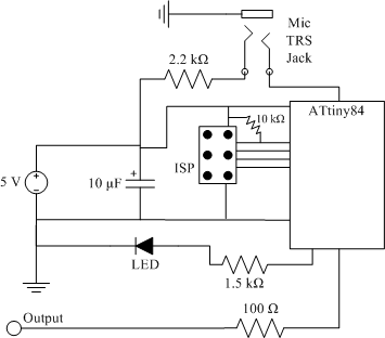
clap sensor construction
The clap sensor is a straightforward circuit that consists of a PC microphone, a microcontroller, and an output. The circuit design features the ATtiny84 microcontroller, chosen for familiarity with the AVR architecture and accessibility to necessary tools. The ATtiny84 is...

Automatic Switch Project
Model railroad turnouts, often referred to as switches, can be controlled in various ways. The simplest method is manual control, operated by hand. Remote activation is typically achieved through pneumatic (air) or electrical means. The project discussed in these articles...

Driving circuit schematic
The driving circuit depicted in Figure 18-12 consists of a connection between the driving portion, the microcontroller, and the air conditioning operation components of the bridge. The microcontroller's digital signal levels from ports P4.0 to P4.3 (approximately 12 feet) and...

Microcontroller Based Telephone Remote Control Circuit
This device enables remote control of various appliances (up to eight with suitable add-on expansion boards) such as lights, water heaters, air conditioning, plant watering systems, alarms, etc., via a relay. It allows users to perform actions such as watering...

Sensor Circuit Of Analog Line Follower Robot
The following circuit illustrates the sensor circuit of an analog line follower robot. Features include control by a microcontroller and a sensor circuit.
The sensor circuit for an analog line follower robot is designed to detect the presence of a line...

Layout Control Mother Board
The layout control motherboard is designed to facilitate the management of various sections of a layout. It features a microcontroller that connects to the MRNet bus and multiple slots for inexpensive control and sensor boards. All control and sensor boards...

Night Light Saver
A Microchip PIC12C508 8-pin CMOS microcontroller controls a night light, turning it on and off at preset times every day. It is designed to save energy, produce no electromagnetic interference (EMI), and operate without batteries, featuring a built-in lamp fixture...

repair microcontroller circuit
The difference between these two ICs. A microcontroller is a specialized type of microprocessor designed to be self-sufficient and cost-effective, while a microprocessor is typically intended for general-purpose use, such as in personal computers (PCs). The microcontroller integrates several useful...

pc based digital ic tester
Check the following ICs: 7400, 7402, 7404, 7408, 7432, 7486. A Visual Basic program is utilized to display the results on the PC. The microcontroller AT89S52 receives the IC number from the PC, verifies the logic gates with the truth...