


propeller clock amazing illusion
#propeller clock
#LED display
#illusion
#microprocessor
#timing
#motor control
#seven LEDs
#array simulation
#Bob Blick
#educational circuits

Description: A motor spins the propeller, while a small microprocessor tracks time and alters the pattern on seven LEDs with precise timing to create the illusion of a 7 by 30 array of LEDs. This concept, initially developed by Bob Blick, has been replicated and enhanced by many others over time. Propeller clocks are intricate devices that utilize a PIC microcomputer operating at 10 MHz. The PIC serves as the central processing unit, managing the timing and illumination of the LEDs to create the appearance of floating numbers and, in analog mode, hands suspended in mid-air. In this particular version of the clock, the mode and time settings can be adjusted while the propeller spins at approximately 1150 RPM. This functionality is facilitated by precisely aligned photo detectors and LEDs located at the rear of the spinning motor, ensuring that the aesthetic of the clock remains unaffected.
The propeller clock operates on the principle of persistence of vision, where the rapid movement of the propeller combined with the synchronized illumination of the LEDs creates a visual effect that tricks the human eye into perceiving static images. The motor is typically a brushless DC motor, selected for its efficiency and ability to maintain a constant speed, which is crucial for the accurate timing necessary for the illusion to work effectively.
The PIC microcontroller is programmed with a specific algorithm that determines the timing of each LED based on the rotational speed of the propeller. The microcontroller receives input from the photo detectors, which detect the position of the propeller blades and provide feedback to ensure that the LEDs light up at the correct moment. The use of photo detectors minimizes the impact on the visual appearance of the clock, as they are discreetly placed and do not interfere with the spinning propeller's aesthetics.
The clock features multiple modes, including a digital display mode that shows numerical time and an analog mode that simulates clock hands. Users can switch between these modes through a user interface that may consist of buttons or touch sensors, designed to be accessible even while the clock is in motion. This innovative design not only enhances user experience but also showcases the advanced engineering involved in creating a visually captivating timepiece.
Overall, the propeller clock exemplifies a blend of mechanical and electronic engineering, demonstrating how precise timing, sensor integration, and visual effects can create an engaging and functional device.A motor spins the "propeller", and a small microprocessor keeps track of time and changes the pattern on seven LEDs with exact timing to simulate a 7 by 30 array of LEDs. It is an illusion, but it works nicely. Propeller clocks were to my knowledge first started by Bob Blick then many people started copying his idea and adding certain improvements
along the way. Propclocks are really pretty complex devices, utilizing a PIC microcomputer that performs instructions at 10mhz. The PIC is the brain of the device and does most of the work involved in making the LEDs light up at just the right time so that it appears there are numbers, and in the analog mode hands suspened in mid air.
On my version of the clock you change the mode and time setting while it is still spinning at about 1150 PRM. This is done through carefully alligned photo detectors and LEDs. These sensors are located on the rear of the spinning motor so they dont affect the look of the clock at all.
The propeller clock operates on the principle of persistence of vision, where the rapid movement of the propeller combined with the synchronized illumination of the LEDs creates a visual effect that tricks the human eye into perceiving static images. The motor is typically a brushless DC motor, selected for its efficiency and ability to maintain a constant speed, which is crucial for the accurate timing necessary for the illusion to work effectively.
The PIC microcontroller is programmed with a specific algorithm that determines the timing of each LED based on the rotational speed of the propeller. The microcontroller receives input from the photo detectors, which detect the position of the propeller blades and provide feedback to ensure that the LEDs light up at the correct moment. The use of photo detectors minimizes the impact on the visual appearance of the clock, as they are discreetly placed and do not interfere with the spinning propeller's aesthetics.
The clock features multiple modes, including a digital display mode that shows numerical time and an analog mode that simulates clock hands. Users can switch between these modes through a user interface that may consist of buttons or touch sensors, designed to be accessible even while the clock is in motion. This innovative design not only enhances user experience but also showcases the advanced engineering involved in creating a visually captivating timepiece.
Overall, the propeller clock exemplifies a blend of mechanical and electronic engineering, demonstrating how precise timing, sensor integration, and visual effects can create an engaging and functional device.A motor spins the "propeller", and a small microprocessor keeps track of time and changes the pattern on seven LEDs with exact timing to simulate a 7 by 30 array of LEDs. It is an illusion, but it works nicely. Propeller clocks were to my knowledge first started by Bob Blick then many people started copying his idea and adding certain improvements
along the way. Propclocks are really pretty complex devices, utilizing a PIC microcomputer that performs instructions at 10mhz. The PIC is the brain of the device and does most of the work involved in making the LEDs light up at just the right time so that it appears there are numbers, and in the analog mode hands suspened in mid air.
On my version of the clock you change the mode and time setting while it is still spinning at about 1150 PRM. This is done through carefully alligned photo detectors and LEDs. These sensors are located on the rear of the spinning motor so they dont affect the look of the clock at all.

LED dot display based Battery charge level indicator circuit diagram
In various situations, it is necessary to indicate the amount of battery charge using methods such as LED dot displays or LED bar displays. This circuit utilizes the LM3914 integrated circuit to serve as a battery charge indicator with an...

The LED car voltmeter (3)
The LED car voltmeter comprises a filter circuit, a voltage distribution filter circuit, a voltage amplifier circuit, and an LED display circuit, as illustrated in Figure 7-77. The regulator filter circuit includes a 3-terminal IC (IC1) and a filter capacitor...

Motor control circuit for forward and reverse phase induction
This is the power diagram for motor forward and reverse operation. To change the motor direction, one polarity must be altered, for example, changing R to S. For detailed information, please refer to the following.
The described power diagram illustrates a...
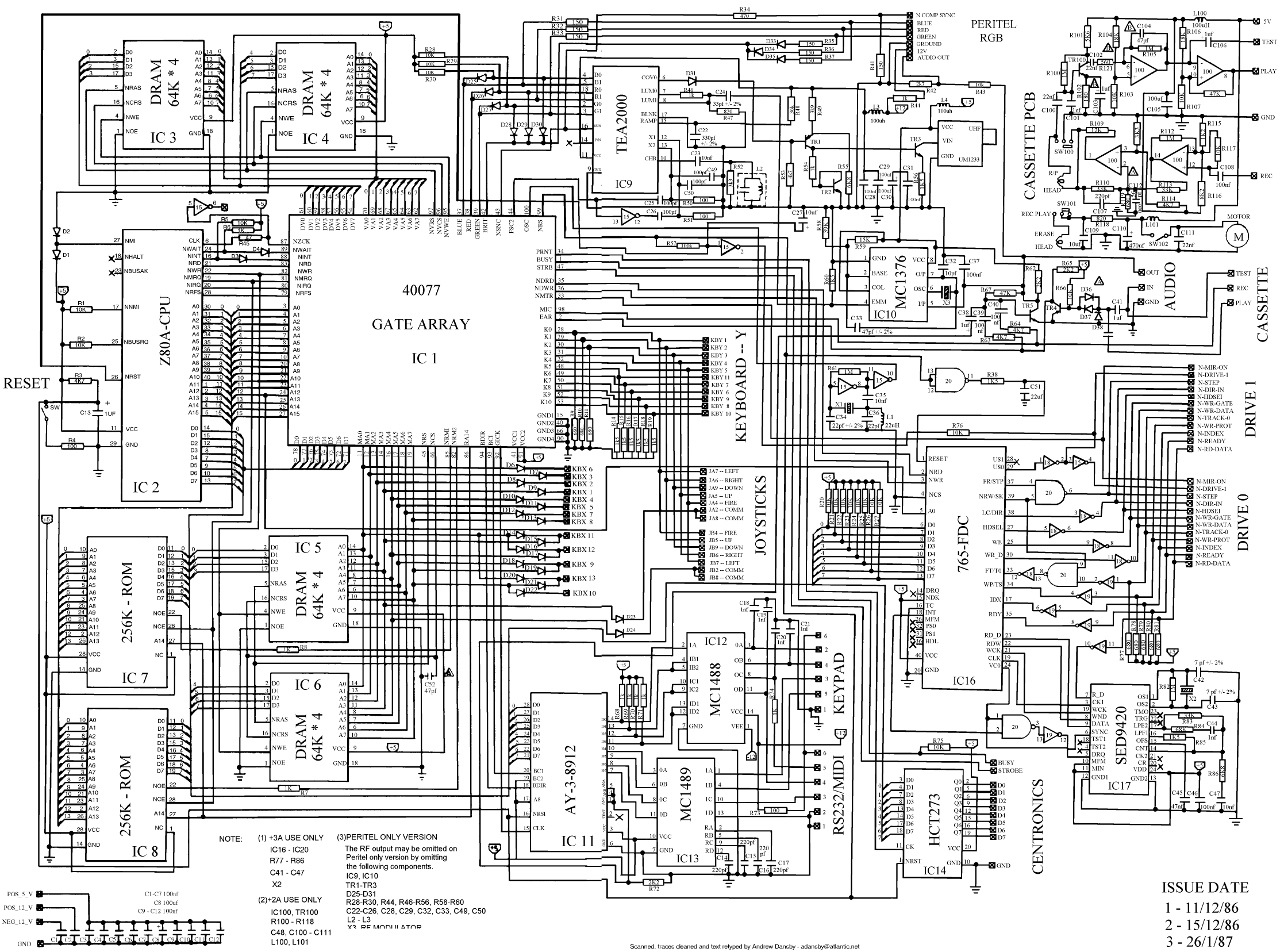
microprocessor Map processor to circuit diagram
How the processor produces 3 as the output. This question may be challenging to answer in simple terms. If so, a link to a book would be helpful.
The process by which a processor generates the output of the number 3...

2Y-Y-2 - connection four-speed motor switch control circuit
The 3-119 circuit shown in the figure combines switch SA to realize the stator windings, specifically the 2, Y, and 2Y connections, which correspond to the motor speed n1.
The 3-119 circuit is designed to facilitate the control of motor speed...

5-motor hexapod circuit
This circuit has a long history, originating from an idea by Rich Piotter and later refined by Wilf Rigter and Bruce Robinson. The final result does not include the necessary motor drivers, which are typically H-bridge based, but presents a...

5x7 LED display schematic
Your 5x7 display is my favourite toy; the tunes and graphics in the elevator display always impress my mates! Since building the display I developed my own 400 dot matrix using a pic and the SN74154 4bit binary to 1...
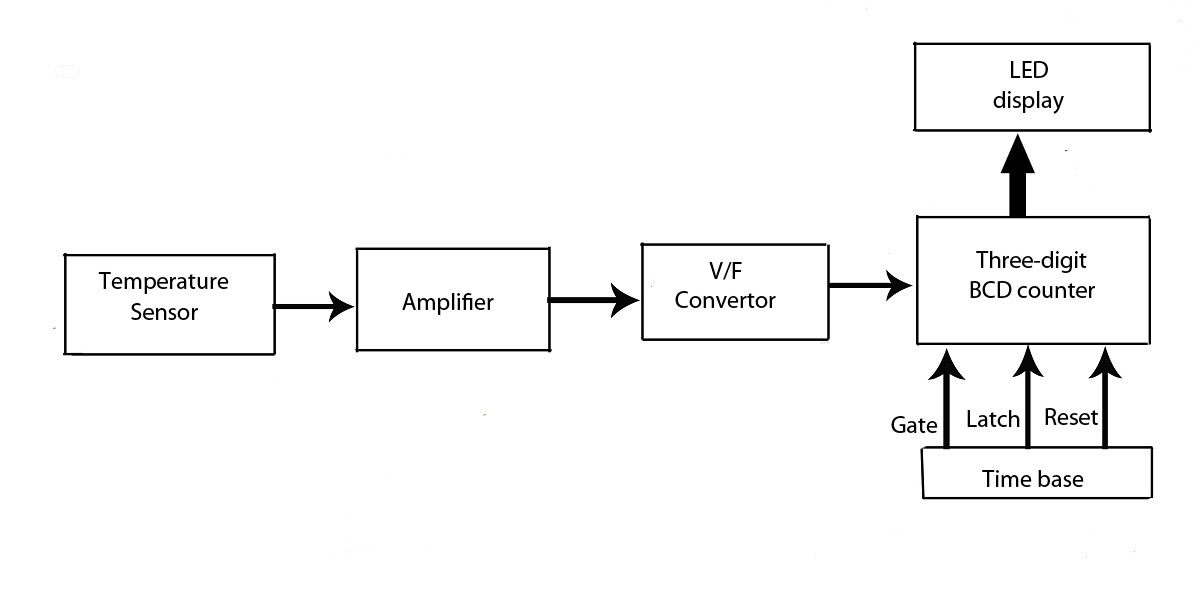
Advanced LED Temperature Indicator
This verified project provides an idea, circuit, and operation of the LED display temperature indicator. It features a digital temperature indicator utilizing a voltage-to-frequency (V/F) converter, along with various electronic projects.
The LED display temperature indicator is designed to provide a...
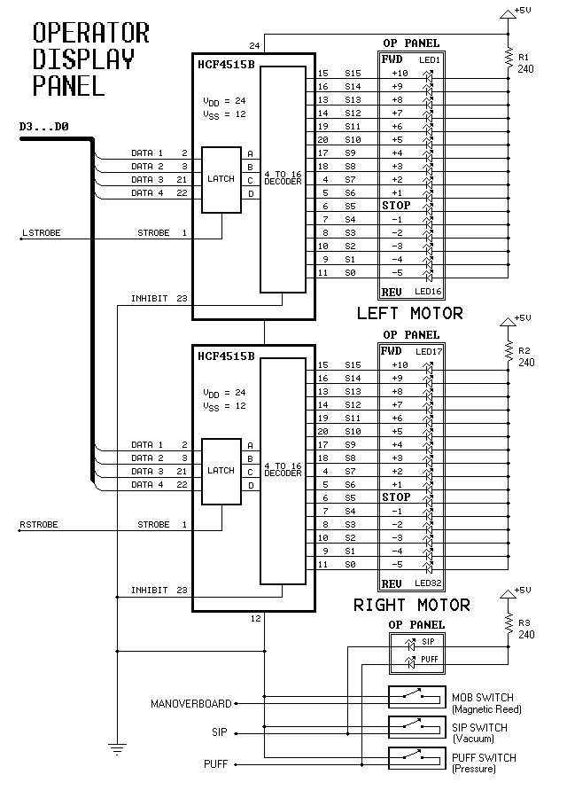
Dual-Motor SIP&PUFF Controlled Kayak System
The YouTube video below demonstrates the quick and easy setup of the system at the launch site.
The provided description indicates a focus on the efficiency of system installation at a launch site, as showcased in a YouTube video. In an...