


PWM fan controller with PIC 12F675
#PIC 12F675
#PWM
#fan controller
#temperature sensor
#NPN transistor
#LED indicator
#duty cycle
#motor control
#optical components

Description: The temperature sensor U2 needs to be located next to the item being monitored. As the temperature increases the motor duty cycle will increase. D1 and R2 are optical components, they only need to be installed for a visual indication of the current duty cycle. Q1 is a 2N4001 NPN transistor. Resistors are all 1/4 Watt. D1 is a blue LED.
The circuit described involves a temperature sensing and control mechanism utilizing a temperature sensor (U2) placed in close proximity to the monitored item. The sensor's role is to detect temperature changes, which subsequently modulate the duty cycle of a motor. As the temperature rises, the control circuit will increase the duty cycle, allowing for proportional control over the motor's speed or power output.
The optical components D1 and R2 serve a dual purpose: providing visual feedback regarding the current duty cycle and enhancing user interaction with the circuit. D1, a blue LED, will illuminate in accordance with the duty cycle, allowing users to easily gauge the operational state of the motor. R2, likely a current-limiting resistor, ensures that the LED operates within its specified current rating, preventing damage.
The circuit utilizes Q1, a 2N4001 NPN transistor, as a switching element. This transistor will act as an interface between the control signal from the temperature sensor and the motor's power supply. When the temperature exceeds a predetermined threshold, the sensor activates Q1, allowing current to flow through the motor circuit, thereby increasing the motor's duty cycle. The choice of a 2N4001 transistor suggests that the circuit is designed for moderate power applications, given its voltage and current ratings.
All resistors in the circuit are specified as 1/4 Watt, indicating that they are suitable for low-power applications. This specification is critical for ensuring that the components can handle the power dissipation without overheating. Proper selection of resistor values will be necessary to fine-tune the performance of the LED and the transistor's switching characteristics.
Overall, this circuit design integrates temperature sensing with motor control and visual indication, creating an efficient and user-friendly monitoring system. Careful attention to component placement, power ratings, and circuit connections will be essential for optimal performance and reliability.The temperature sensor U2 needs to be located next to the item being monitored. As the temperature increases the motor duty cycle will increase. D1 and R2 are optical components, they only need to be installed for a visual indication of the current duty cycle. Q1 is a 2N4001 NPN transistor. Resistors are all 1/4 Watt. D1 is a blue LED.
The circuit described involves a temperature sensing and control mechanism utilizing a temperature sensor (U2) placed in close proximity to the monitored item. The sensor's role is to detect temperature changes, which subsequently modulate the duty cycle of a motor. As the temperature rises, the control circuit will increase the duty cycle, allowing for proportional control over the motor's speed or power output.
The optical components D1 and R2 serve a dual purpose: providing visual feedback regarding the current duty cycle and enhancing user interaction with the circuit. D1, a blue LED, will illuminate in accordance with the duty cycle, allowing users to easily gauge the operational state of the motor. R2, likely a current-limiting resistor, ensures that the LED operates within its specified current rating, preventing damage.
The circuit utilizes Q1, a 2N4001 NPN transistor, as a switching element. This transistor will act as an interface between the control signal from the temperature sensor and the motor's power supply. When the temperature exceeds a predetermined threshold, the sensor activates Q1, allowing current to flow through the motor circuit, thereby increasing the motor's duty cycle. The choice of a 2N4001 transistor suggests that the circuit is designed for moderate power applications, given its voltage and current ratings.
All resistors in the circuit are specified as 1/4 Watt, indicating that they are suitable for low-power applications. This specification is critical for ensuring that the components can handle the power dissipation without overheating. Proper selection of resistor values will be necessary to fine-tune the performance of the LED and the transistor's switching characteristics.
Overall, this circuit design integrates temperature sensing with motor control and visual indication, creating an efficient and user-friendly monitoring system. Careful attention to component placement, power ratings, and circuit connections will be essential for optimal performance and reliability.The temperature sensor U2 needs to be located next to the item being monitored. As the temperature increases the motor duty cycle will increase. D1 and R2 are optical components, they only need to be installed for a visual indication of the current duty cycle. Q1 is a 2N4001 NPN transistor. Resistors are all 1/4 Watt. D1 is a blue LED.

Universal motor control
When the time delay expires, SCR1 conducts and removes the gate signal from SCR2, which stops the motor. Both the time delay and motor speed are adjustable by potentiometers R2 and R3. If heavier motor loads are anticipated, use the...

LM134-LM10 Thermometer/Temperature Sensor
Using LM134 and LM10 integrated circuits, a thermometer can be constructed with a sensing range of -55 to 150 °C. The ideal meter for this circuit is a 0-200 µA.
The proposed thermometer circuit utilizes the LM134, a current source IC,...

Internal functional block diagram of NCP5201
The NCP5201 chip contains two sets of PWM signal generating circuits, each with a dedicated set of output pins. These circuits produce two opposite phase PWM signals, which are applied to the gates of three field effect transistors. This arrangement...
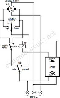
To Automate Rolling Shutter Motor
To automate the opening and closing of a rolling shutter using a time-controlled switch, additional wiring will be necessary.
To implement an automated system for a rolling shutter, a time-controlled switch can be utilized to manage the operation of the shutter....
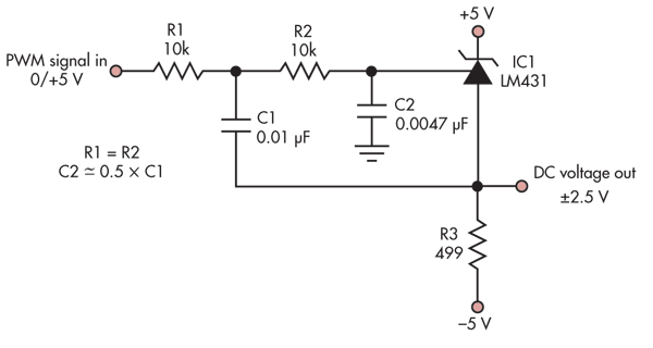
Digitally adjustable precision reference driven via PWM
This simple circuit converts a 5V PWM signal into a variable precision reference voltage with a range of -2.5V to +2.5V. Many designs, such as a digitally controlled power supply or a programmable dummy load, require a Digital to Analog...

DC motor PWM speed control
The 555 IC is wired as an astable and the frequency is constant and independent of the duty cycle, as the total resistance (R charge + R discharge, notice the diode) is constant and equal to 22Kohm (giving a frequency...

My Motors got me to Tap into Radiant Energy
A new user is seeking to share information about their experiences on this platform.
The user expresses a desire to communicate and engage with the community regarding their experiences. This indicates an interest in exchanging knowledge and possibly seeking assistance or...
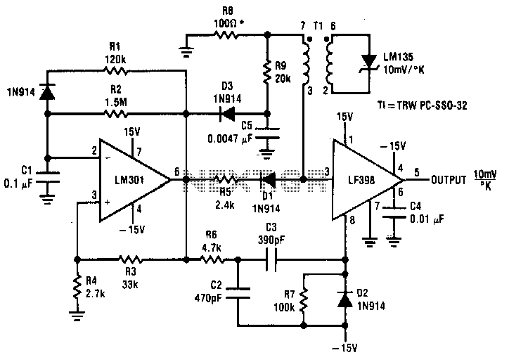
Two-simple-temperature-to-time-converters
Both converters utilize CMOS inverters. Figure 105-1A illustrates a free-running circuit where both pulse duration and pulse pause are influenced by the temperature of diode D8. This configuration is suitable for applications where synchronization between the converter and other systems...

Cold Sensor
The resistance decreases when the temperature in its vicinity increases by one degree or more. Component: LED, Buzzer, Transistor, Capacitor, etc.
The described component exhibits a negative temperature coefficient, which means that its resistance decreases as ambient temperature increases. This behavior...