


Schematic diagram of clock circuit composed of AT89C2051

Description: The circuit design incorporates an anodic Nixie tube for the LED display. It utilizes the LQ5101BS general luminous diode, with the driving transistor being either the 2SA1015 or 2SC1815 types, which are readily available. Additionally, low-power transistors such as the S9012, S9013, S9014, 2N5401, and 2N5555 can also be used. There are no specific requirements for other components. To facilitate experimentation, the monolithic AT89C2051 microcontroller can be mounted using a DIP20P socket. The program does not require debugging after being written and can be easily copied to the AT89C2051. Notably, the AT89C2051 is a flash memory device, allowing the program to be rewritten multiple times, which simplifies the experimental process.
The circuit utilizes an anodic Nixie tube as the primary display element, which operates by illuminating specific segments to represent numerical values. The LQ5101BS general luminous diode serves as the light source, providing adequate brightness for visibility. The driving transistors, either the 2SA1015 or 2SC1815, are selected for their availability and reliability in switching applications. These transistors control the current flowing through the Nixie tube, ensuring that the segments light up correctly based on the signals received from the microcontroller.
Alternative low-power transistors, including the S9012, S9013, S9014, 2N5401, and 2N5555, can be employed if the design requires components with different specifications or performance characteristics. These transistors are suitable for driving low-current applications, making them ideal for use in conjunction with the Nixie tube.
The AT89C2051 microcontroller is an essential part of this circuit, and its integration is facilitated by the DIP20P socket, which simplifies the connection process. This microcontroller is particularly advantageous due to its flash memory capability, allowing users to write and rewrite programs easily without the need for extensive debugging. This feature is beneficial for rapid prototyping and experimentation, as it enables quick iterations of program modifications.
The overall design is straightforward, with no stringent requirements for additional components, making it accessible for experimentation and educational purposes. The combination of the Nixie tube display, the selected driving transistors, and the programmable microcontroller creates a versatile circuit that can be adapted for various applications in electronic learning and prototyping environments.The circuit composition determines that the LED adopts anodic Nixie tube. It can use LQ5101BS general luminous diode and the driving triode can use 2SA1015 or 2SC1815 types which is easy to gain. Of cause, the triode can also use low-power triode such as S9012, S9013, S9014, 2N5401, and 2N5555 etc.
There are no special requirements for other componen ts. To make the experiment easier, monolithic AT89C2051 can use DIP20P socket. The program need no debugging after written, and it can be copied to AT89C2051. What worth mentioning is that AT89C2051 is a flash program memorizer, and the program can be rewritten repeatedly, which makes it very easy to conduct experiments.
The circuit utilizes an anodic Nixie tube as the primary display element, which operates by illuminating specific segments to represent numerical values. The LQ5101BS general luminous diode serves as the light source, providing adequate brightness for visibility. The driving transistors, either the 2SA1015 or 2SC1815, are selected for their availability and reliability in switching applications. These transistors control the current flowing through the Nixie tube, ensuring that the segments light up correctly based on the signals received from the microcontroller.
Alternative low-power transistors, including the S9012, S9013, S9014, 2N5401, and 2N5555, can be employed if the design requires components with different specifications or performance characteristics. These transistors are suitable for driving low-current applications, making them ideal for use in conjunction with the Nixie tube.
The AT89C2051 microcontroller is an essential part of this circuit, and its integration is facilitated by the DIP20P socket, which simplifies the connection process. This microcontroller is particularly advantageous due to its flash memory capability, allowing users to write and rewrite programs easily without the need for extensive debugging. This feature is beneficial for rapid prototyping and experimentation, as it enables quick iterations of program modifications.
The overall design is straightforward, with no stringent requirements for additional components, making it accessible for experimentation and educational purposes. The combination of the Nixie tube display, the selected driving transistors, and the programmable microcontroller creates a versatile circuit that can be adapted for various applications in electronic learning and prototyping environments.The circuit composition determines that the LED adopts anodic Nixie tube. It can use LQ5101BS general luminous diode and the driving triode can use 2SA1015 or 2SC1815 types which is easy to gain. Of cause, the triode can also use low-power triode such as S9012, S9013, S9014, 2N5401, and 2N5555 etc.
There are no special requirements for other componen ts. To make the experiment easier, monolithic AT89C2051 can use DIP20P socket. The program need no debugging after written, and it can be copied to AT89C2051. What worth mentioning is that AT89C2051 is a flash program memorizer, and the program can be rewritten repeatedly, which makes it very easy to conduct experiments.

LED flasher with two transistors
This circuit will flash a bright LED 5000mcd as an intention getting device or fake car alarm. More: Component values are not critical and different transistors may be used.
This circuit functions as a visual alert system by utilizing a high-brightness...

Mains Voltage Indicator with a LED
A need exists for a 220V AC line light display or main voltage monitor due to frequent electrical issues in a home.
To create a 220V AC line light display or voltage monitor, a circuit can be designed using a combination...
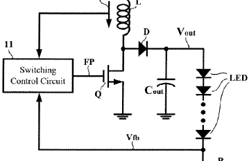
Dimming Control Circuit for LEDs
A dimming control circuit generates a dimming control signal to determine the brightness of at least one light-emitting diode. The dimming control signal consists of multiple bright-dark cycles, each comprising a bright phase and a dark phase. The bright phase...

putting a led instead of an incandescent bulb on my bike
A few days ago, the rear light burned out. While it is not critical, the front light is essential for nighttime visibility. The reflective red plastic at the back provides some safety, so there is no immediate concern. Nonetheless, a...

led tube light using transformer
The use of white LEDs for home illumination is gaining popularity due to their high power efficiency. The diagram illustrates a simple circuit configuration that consists of multiple LEDs arranged in both series and parallel. In the LED tube light...

Aquarium Led Lighting Circuit
This colorful backlit aquarium light provides a natural appearance to the aquarium tank. The aquarium LED lighting circuit automatically turns on at sunset.
The aquarium LED lighting system enhances the aesthetic appeal of the aquarium by simulating natural lighting conditions. The...

Led Flasher with a BC547 NPN transistor
This is a novel flasher circuit using a single driver transistor that takes its flash-rate from a flashing LED. The flasher in the photo is 3mm. An ordinary LED will not work. The flash rate cannot be altered by the...
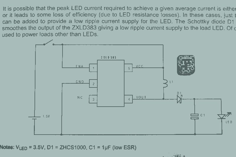
LED lights using Joule Thief circuits
It may seem that due to the numerous flashlight projects undertaken, there is a significant collection of lights. The inductor can be altered to set the current level, but the total current fluctuates with the battery supply, decreasing as the...

Economical Desk Lamp For Camping
This LED lamp was originally designed for use on a budget solar-charged 12V electrical system. It is bright enough for comfortable reading at night and features constant LED brightness with diminishing battery voltage. The circuit uses six high-brightness white LEDs...