


Serial programmer circuit for AT89Sx MCUs

Description: A simple RS-232 ISP programmer designed for AT89Sx devices, intended for educational purposes and hobbyist use. It has been tested with the AT89S2051 and AT89S8253 microcontrollers, utilizing a USB to serial port converter cable equipped with a PL2303 chip.
The microcontroller within the programmer can operate even when the computer is turned off or disconnected. The transistors used in the design can be substituted with nearly any universal low-frequency transistors that have the same pin configuration. Incorrect resistor values may lead to malfunction, so it is advisable to prototype the circuit on a solderless breadboard before committing to a printed circuit board (PCB) design and soldering. The RS-232 connector on the board is of the female type. A reset button is included to reset the microcontroller connected to the programmer. It is important to note that hardware connected to the microcontroller ports may cause the programmer to malfunction. The power supply requirement is between 8 to 30 volts, with the programmer functioning at 5 volts. LED1 indicates when the power is on, while LED2 signifies PC activity or an uninitialized programmer. The ISP programming cable allows the programmer to program a microcontroller, for example, on a breadboard or a PCB. However, it should be noted that communication can only occur with one microcontroller at a time, necessitating the removal of the microcontroller placed in the socket on the programmer board before programming another.
The RS-232 ISP programmer circuit is a straightforward design that facilitates the programming of AT89Sx devices through a serial interface. The system architecture includes a microcontroller that manages the programming process and interfaces with the computer through the RS-232 protocol. The use of the PL2303 chip allows for seamless USB to serial communication, which is essential for modern computer systems lacking traditional serial ports.
The power supply circuit should include voltage regulation to ensure that the microcontroller operates reliably at 5V, even if the input voltage varies between 8V and 30V. The inclusion of a reset button adds a layer of convenience, allowing users to easily reset the microcontroller without needing to power down the entire system.
The programmer's design should incorporate indicators such as LED1 and LED2 to provide visual feedback on the operational status. LED1 serves as a power indicator, while LED2 can be used for debugging purposes by indicating when the programmer is actively communicating with the computer or when it is uninitialized.
In terms of hardware considerations, careful selection of resistors and transistors is crucial to avoid potential malfunctions. The circuit layout should be optimized to minimize noise and interference, particularly in the signal lines connecting to the microcontroller ports. To facilitate ease of use, the RS-232 connector should be clearly labeled, and the ISP programming cable should be designed to connect securely to both the programmer and the target microcontroller.
For prototyping, a solderless breadboard allows for flexibility and experimentation with component values and arrangements before finalizing the design on a PCB. This approach helps identify any potential issues in the circuit design, particularly with respect to the interactions between the programmer and the microcontroller being programmed.Simple RS-232 ISP programmer for AT89Sx devices. This device is intended for education purposes and for hobbyists. It has been tested with AT89S2051 and AT89S8253 along with USB to serial port converter cable (with PL2303 chip). MCU in programmer can work while computer is turned off or disconnected. Transistors can be replaced with almost any universal low frequency transistors with the same pinout. Bad resistor values may cause malfunction. It might be a good idea to try it in solderless breadboard before making PCB and soldering. RS-232 connector on the board is female. Reset button resets MCU connected to the programmer. Hardware connected to the MCU ports may cause programmer malfunction. Power supply: 8 → 30 V (Programmer work with 5V) LED1: Indicates power on LED2: Indicates PC activity or uninitilized programmer ISP programming cable: Trough this interface programmer should be able to program MCU for instance in breadboard or some PCB.
But remember it can comunicate with only one MCU at the time. So MCU placed in the socket on the programmer board must be removed firts.
The microcontroller within the programmer can operate even when the computer is turned off or disconnected. The transistors used in the design can be substituted with nearly any universal low-frequency transistors that have the same pin configuration. Incorrect resistor values may lead to malfunction, so it is advisable to prototype the circuit on a solderless breadboard before committing to a printed circuit board (PCB) design and soldering. The RS-232 connector on the board is of the female type. A reset button is included to reset the microcontroller connected to the programmer. It is important to note that hardware connected to the microcontroller ports may cause the programmer to malfunction. The power supply requirement is between 8 to 30 volts, with the programmer functioning at 5 volts. LED1 indicates when the power is on, while LED2 signifies PC activity or an uninitialized programmer. The ISP programming cable allows the programmer to program a microcontroller, for example, on a breadboard or a PCB. However, it should be noted that communication can only occur with one microcontroller at a time, necessitating the removal of the microcontroller placed in the socket on the programmer board before programming another.
The RS-232 ISP programmer circuit is a straightforward design that facilitates the programming of AT89Sx devices through a serial interface. The system architecture includes a microcontroller that manages the programming process and interfaces with the computer through the RS-232 protocol. The use of the PL2303 chip allows for seamless USB to serial communication, which is essential for modern computer systems lacking traditional serial ports.
The power supply circuit should include voltage regulation to ensure that the microcontroller operates reliably at 5V, even if the input voltage varies between 8V and 30V. The inclusion of a reset button adds a layer of convenience, allowing users to easily reset the microcontroller without needing to power down the entire system.
The programmer's design should incorporate indicators such as LED1 and LED2 to provide visual feedback on the operational status. LED1 serves as a power indicator, while LED2 can be used for debugging purposes by indicating when the programmer is actively communicating with the computer or when it is uninitialized.
In terms of hardware considerations, careful selection of resistors and transistors is crucial to avoid potential malfunctions. The circuit layout should be optimized to minimize noise and interference, particularly in the signal lines connecting to the microcontroller ports. To facilitate ease of use, the RS-232 connector should be clearly labeled, and the ISP programming cable should be designed to connect securely to both the programmer and the target microcontroller.
For prototyping, a solderless breadboard allows for flexibility and experimentation with component values and arrangements before finalizing the design on a PCB. This approach helps identify any potential issues in the circuit design, particularly with respect to the interactions between the programmer and the microcontroller being programmed.Simple RS-232 ISP programmer for AT89Sx devices. This device is intended for education purposes and for hobbyists. It has been tested with AT89S2051 and AT89S8253 along with USB to serial port converter cable (with PL2303 chip). MCU in programmer can work while computer is turned off or disconnected. Transistors can be replaced with almost any universal low frequency transistors with the same pinout. Bad resistor values may cause malfunction. It might be a good idea to try it in solderless breadboard before making PCB and soldering. RS-232 connector on the board is female. Reset button resets MCU connected to the programmer. Hardware connected to the MCU ports may cause programmer malfunction. Power supply: 8 → 30 V (Programmer work with 5V) LED1: Indicates power on LED2: Indicates PC activity or uninitilized programmer ISP programming cable: Trough this interface programmer should be able to program MCU for instance in breadboard or some PCB.
But remember it can comunicate with only one MCU at the time. So MCU placed in the socket on the programmer board must be removed firts.

Rs232-to-cmos-line-receiver
This RS-232 type line receiver is designed to drive CMOS logic and incorporates a Schmitt-trigger feedback network that provides approximately 1-V input hysteresis, enhancing noise immunity. A potential issue in an interface connecting two devices, each connected to different AC...

RS-232 Laser Transciever circuit
Laser based projects used to be expensive, until the development of solid state lasers. This project is designed for the entry level laser experimenter. The circuit allows any two computers with serial (RS-232) communication capability to communicate over 200 meters...

CMX867A Low Power V.22 Modem
This RS-232 to RS-485 protocol converter utilizes two components to form a complete operational system. The circuit adheres to all EIA and ITU specifications for RS-232 to RS-485 RS422 conversion. It features a robust design capable of handling ±15kV ESD...

RS-232 Laser Transceiver
This project is intended for entry-level laser experimenters. The circuit enables communication between two computers with serial (RS-232) capabilities over a distance of 200 meters using a laser beam. A low-cost transmitter-only circuit is also provided for one-way communication and...

ISP Programmer
ISP Programmer. Please purchase USB programming cables and start using AVR Studio, avrdude, etc. The source code is now considered abandonware and will remain on Sourceforge indefinitely. This software supports programming of Atmel microcontrollers, including 89Sxx (51), ATtiny, ATmega, and...

LTC1045 TTL RS-232 Converter
A simple method to construct a battery-powered RS-232 receiver circuit is illustrated in the schematic diagram below. This circuit converts RS-232 levels to TTL levels.
The RS-232 standard is widely used for serial communication, and it operates at voltage levels that...

RS-232 Protocol Analyser Y Cable
In need for a cheap but effective RS-232 Protocol Analyser? Just make your own Y adaptor to enable the logging or display of data transmitted and/or received in ASCII, Hex, Decimal or Hex-Dump formats. A configuration file is included to...
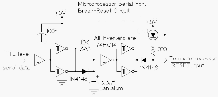
Microprocessor RS-232 Reset
This circuit enables a remote microprocessor to be reset by a controlling host via a remote RS-232 or similar protocol serial line. Utilizing a program loader on the remote host, a program can be downloaded and executed. This functionality allows...

RS-232 Data Switch
This report deals with the design for a small asynchronous serial data switch. The switch architecture allows 14 serial ports supporting a subset of the RS-232 protocol. The requirements for the switch are discussed. The hardware interfaces are described in...