


The MSC1210 Typical External Reset Circuit Schematic
#MSC1210
#reset circuit
#power-on reset
#external reset
#watchdog timer
#brownout reset
#Flash Memory
#10kOhm resistor
#microcontroller

Description: A flash memory schematic can be created using various reset sources, including power-on reset, external reset, software reset, watchdog timer reset, and brownout reset. The accompanying figure illustrates a recommended external reset circuit for the MSC1210, which includes a suggestion for a 10 kΩ resistor for any configuration of this reset type. According to the MSC1210 datasheet, an external reset is performed by driving the RST pin high for two periods of tOSC. This action halts device operation, ceases crystal oscillation, and causes all digital pins to be pulled high. Subsequently, the RST pin is driven low to initiate the reset procedure.
The flash memory schematic involving the MSC1210 microcontroller incorporates several critical reset mechanisms that ensure reliable operation across various scenarios. The power-on reset provides an initial state for the device when power is applied, while the external reset allows for manual or external control over the device's state. Software reset can be triggered through specific instructions in the code, enabling the program to recover from errors or to restart processes without physical intervention.
The watchdog timer reset serves as a fail-safe mechanism, resetting the device if it becomes unresponsive due to software malfunctions. The brownout reset protects the device from operating under insufficient voltage conditions, which could lead to unpredictable behavior.
The recommended external reset circuit for the MSC1210, featuring a 10 kΩ resistor, is designed to ensure that the RST pin is adequately pulled high during the reset process. This resistor value is optimal for balancing the response time and power consumption of the circuit. When the RST pin is driven high for two tOSC periods, it effectively halts all operations, ensuring that the microcontroller is in a safe state before executing a reset. After this period, pulling the RST pin low initiates the reset sequence, allowing the device to resume normal operation.
In summary, this flash memory schematic provides a robust framework for managing various reset conditions in the MSC1210 microcontroller, ensuring reliable performance and stability in electronic applications.and Flash Memory schematic that can be done from the following sources: power-on reset, external reset, software reset, watchdog timer reset, and brownout reset. The figure (click to enlarge) shows a recommended external reset circuit for the MSC1210 with the serial 10kOhm resistor recomendation for any configuration of this reset type.
According t othe MSC1210 datasheet, you willperform an external resetby taking RST pin high for two tOSC periods as this stops device operation, crystal oscillation, causes all digitall pins to be pulled high from that point and then followed by taking the RST pin low that initiates the reset procedure.
The flash memory schematic involving the MSC1210 microcontroller incorporates several critical reset mechanisms that ensure reliable operation across various scenarios. The power-on reset provides an initial state for the device when power is applied, while the external reset allows for manual or external control over the device's state. Software reset can be triggered through specific instructions in the code, enabling the program to recover from errors or to restart processes without physical intervention.
The watchdog timer reset serves as a fail-safe mechanism, resetting the device if it becomes unresponsive due to software malfunctions. The brownout reset protects the device from operating under insufficient voltage conditions, which could lead to unpredictable behavior.
The recommended external reset circuit for the MSC1210, featuring a 10 kΩ resistor, is designed to ensure that the RST pin is adequately pulled high during the reset process. This resistor value is optimal for balancing the response time and power consumption of the circuit. When the RST pin is driven high for two tOSC periods, it effectively halts all operations, ensuring that the microcontroller is in a safe state before executing a reset. After this period, pulling the RST pin low initiates the reset sequence, allowing the device to resume normal operation.
In summary, this flash memory schematic provides a robust framework for managing various reset conditions in the MSC1210 microcontroller, ensuring reliable performance and stability in electronic applications.and Flash Memory schematic that can be done from the following sources: power-on reset, external reset, software reset, watchdog timer reset, and brownout reset. The figure (click to enlarge) shows a recommended external reset circuit for the MSC1210 with the serial 10kOhm resistor recomendation for any configuration of this reset type.
According t othe MSC1210 datasheet, you willperform an external resetby taking RST pin high for two tOSC periods as this stops device operation, crystal oscillation, causes all digitall pins to be pulled high from that point and then followed by taking the RST pin low that initiates the reset procedure.

Talking Yoda head
The talking Yoda head consists of a Yoda mask and a microcontroller system to achieve the desired operation/effect. The basic operation of the project was specified as follows: The head was to be placed inside a closed box. Upon opening...

Cipher scheme of the module of infrared remote-control between two parties of intellectual family
This system is a control system based on a single-chip computer that allows for remote operation of lighting. The scheme primarily addresses the transmission and reception of signals, as well as program manipulation of various signals once they are processed...

Electronic TIC TAC TOE
This project is not to introduce Tic Tac Toe. Everyone knows this game. It is to introduce two features: bi-coloured LEDs, microcontrollers, and the skill of writing an ALGORITHM. You can use the project to learn the skills of creating...

Low Resource Microcontroller 3 Phase BLDC Motor Speed Controller
This article discusses a minimal resource microcontroller implementation for a three-phase Brushless DC (BLDC) motor, focusing on a closed-loop speed motor controller application based on a Microchip PIC12 device. It demonstrates how minimization techniques can reduce the number of I/O...

Metal detector circuit
The project demonstration has been successfully completed, with the only remaining task being the final project report due on June 15, which will be integrated with a conference paper. This update marks the last entry in the electronic notebook, although...
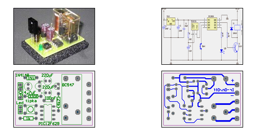
IR On/Off Switch Using Microcontroller
The ability to turn electrical devices ON or OFF using a remote control is a well-established concept, with numerous devices effectively performing this function.
To implement a remote control system for switching electrical devices, a typical schematic would include several key...

MICROCONTROLLER BASED AUTOMATIC ROOM LIGHT CONTROLLER
This project involves an automatic room light controller with a bidirectional visitor counter using a microcontroller. It is designed to manage room lighting and accurately count the number of individuals present. When a person enters the room, the counter increments...

Robo Atmega328p project
This project was designed to introduce a friend to microcontrollers and circuits using various functionalities and spare parts. A PS2 numpad was utilized as the key entry mechanism, which was found at a thrift store and included the necessary connector....

Microcontroller Relay Driver and Interface
Many microcontroller designs typically integrate various interfacing methods. A microcontroller (µC) system can be viewed as a system that reads from inputs.
Microcontroller systems are versatile platforms that facilitate the integration of multiple interfacing methods to interact with various peripherals and...