


Tron Disc with .NET Microframework
#Netduino
#.NET Microframework
#lightshow
#Tron Disc
#hackerspace
#programmable
#LED
#tutorial
#customizable
#electronics
Description: Harford Hackerspace aimed to create a Tron Identity Disc using the Netduino, which enables quick loading of different code versions to modify the disc's functionality. David Powell, Gary W. Cygiel, Jeremy Ashinghurst, Paul King, and Jason McMahon present a simple light show in this tutorial, allowing developers to easily extend the code and hardware to create an interactive game. To initiate the project, a Spin Master Tron Identity Disc replica was purchased and retrofitted, avoiding the need to manufacture a new physical disk and simplifying the project. Placing the Tron Identity Disc on or removing it from a charging station triggers an event handler. When placed on the charger, a pulsating animation starts, and removing the disc resumes the previous animation. The original Deluxe Tron Identity Disc featured six LEDs on the outer ring, which was insufficient. The modified disc now includes 30 LEDs on the outer ring and two LEDs illuminating the inner arc. The project began by opening the disc and removing its four Phillips head screws, followed by the extraction of all electronics, including wires, tilt sensor, LEDs, switch, speaker, and microcontroller board, while ensuring the plastic momentary button was not lost for later use in switching animations. A Dremel with a cutoff wheel was utilized to remove unnecessary plastic to accommodate new electronics. The narrow end of the momentary button was attached to the plastic Tron ring using superglue. An L bracket was cut from acrylic and secured with cyanoacrylate, reinforced with hot glue, and the momentary switch was attached to the L bracket. This modification allowed the original plastic momentary button to activate the new momentary switch. A cardboard circle was cut to mark and arrange the LEDs in an equally spaced circular pattern, with notches cut at an angle to hold the LEDs, preventing short circuits. All components were connected according to schematic diagrams. The MAX7219 IC is capable of controlling 64 LEDs, but only 30 were used for simplified wiring. The circuit is divided into five segments, each containing six LEDs, with all cathodes tied together and connected to a single segment pin on the MAX7219, while the anodes are routed back to digit pins. Each LED in a segment has a designated digit, and segments share digit pins. The Netduino controls the logic level of the digit and segment pins using bit-banged I2C. The schematic serves as the best reference for the LED wiring. The charging system consists of a charging circuit and a detection circuit, with a lithium-ion battery charged from an external power source. The charging circuit, modified from a design by Scott Henion of SHDesigns.org, ensures safe charging. The detection circuit allows the Netduino to recognize when charging occurs. The LM317 acts as an adjustable voltage regulator, utilized here for voltage regulation. A 470-ohm resistor forms a voltage divider with a 1k-ohm potentiometer and a 2.2k-ohm resistor to set the output voltage at 8.4V. Since lithium-ion batteries require constant current-constant voltage charging, a transistor and resistor limit the current in the circuit. When the charge current exceeds a certain threshold, the voltage drop across the resistor activates the transistor, allowing it to conduct.
The design of the Tron Identity Disc project integrates various electronic components to achieve the desired functionality. The use of the MAX7219 IC simplifies the control of multiple LEDs, allowing for intricate light patterns to be displayed. The division of the circuit into segments not only eases wiring complexity but also enhances the visual effects by enabling independent control of LED groups. The choice of the Netduino as the microcontroller provides flexibility in programming and rapid prototyping, facilitating the development of interactive features.
The charging circuit's design is critical for ensuring the longevity and safety of the lithium-ion battery. The LM317 voltage regulator is essential for maintaining the appropriate charging voltage, while the combination of resistors and the transistor provides a reliable method for current regulation. This careful consideration of the charging parameters is vital, as improper charging can lead to battery damage or reduced performance.
The physical modifications made to the original Tron Identity Disc highlight the project's innovative approach. By retrofitting an existing product, the team was able to focus on enhancing functionality without the need for extensive fabrication. The integration of a momentary switch and the careful arrangement of LEDs demonstrates a thoughtful design process that prioritizes both aesthetics and usability.
Overall, the project exemplifies a successful blend of electronics engineering and creative design, resulting in a customizable and interactive device that pays homage to the original Tron Identity Disc while enhancing its capabilities.Harford Hackerspace wanted to make our own Tron Identity Disc using the Netduino, allowing us to quickly load different versions of code to change the disc`s functionality. David Powell, Gary W. Cygiel, Jeremy Ashinghurst, Paul King, Jason McMahon present a simple lightshow in this tutorial, developers can easily extend the code and hardware to p
roduce an interactive game. To get started, we purchased and retrofitted a Spin Master Tron Identity Disc replica, which kept us from having to create a new physical disk, and so sidestepped the most difficult aspect of the project. Placing the Tron Idenity Disc on or removing the Tron Identity Disc from a charging station will raise an event handler.
Placing the disc on the charger will start a pulsating animation. Removing the disc will resume the previous animation. The original Deluxe Tron Identity Disc contained six LED on the outer ring, which left much to be desired. Our modified disc includes 30 LEDs on the outer ring and two LEDs illuminating the inner arc. To get started, we opened the disc by removing its four Phillips head screws. Next, we removed all electronics including the wires, tilt sensor, LEDs, switch, speaker, and microcontroller board, taking care to not lose the plastic momentary button, since we later used it to switch between our animations.
Then, we used a Dremel with a cutoff wheel to remove any unnecessary plastic in order to make room our own electronics. See Figure 1. As shown in Figure 2, we used superglue to attach the narrow end of the momentary button to the plastic Tron ring.
Then, using the Dremel, we cut a small L bracket from a scrap piece of acrylic and attached it with cyanoacrylate. We reinforced the L bracket using hot glue and applied a small amount of cyanoacrylate to the momentary switch and attached it to the L bracket.
Consequently, the original plastic momentary button now activates our momentary switch. Next, we cut a circle from a piece of cardboard. Using a straight edge, we carefully marked the location of each LED to arrange an equally spaced circular pattern. Then, with a hobby razor knife, we cut notches in the cardboard at a slight angle to hold the LEDs. An additional benefit of the cardboard is it helps keep the anodes and cathodes from shorting out. Next, we connected all of the components together per the following schematic diagrams. The MAX7219 IC is capable of controlling 64 LEDs. However, we chose to use only 30 in order to simplify of wiring. The circuit is divided into five segments, each containing six LEDs. In each segment, all the cathodes are tied together and then tied to a single segment pin on the MAX7219 and the anodes are routed back to its digit pins.
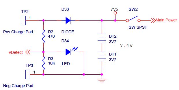
There is one digit for each LED in the segment and the segments share digit pins. The Netduino controls the logic level of the digit and segment pins using bit-banged I2C. All that said, the schematic is the best reference as to how the LEDs were wired. The charging system is comprised of a charging circuit and a detection circuit. A lithium-ion battery inside the disc is charged from an external power source. The charging circuit, which was modified from a design by Scott Henion of SHDesigns. org, provides a method of safe charging. The detection circuit allows the Netduino to know when it`s being charged. The LM317 is an adjustable voltage regulator that may also be used as an adjustable constant-current source. In this case, it`s used as a voltage regulator. The 470 ohm resistor forms a voltage divider with the 1k ohm potentiometer and the 2. 2k ohm resistor to set the output voltage at 8. 4V. Since lithium-ion batteries should be charged using constant current-constant voltage, the transistor and resistor form the current limiting in the circuit.
When the charge current reaches a certain threshold, the resistor`s voltage drop exceeds the turn-on voltage of the transistor and the transistor starts to conduct.
The design of the Tron Identity Disc project integrates various electronic components to achieve the desired functionality. The use of the MAX7219 IC simplifies the control of multiple LEDs, allowing for intricate light patterns to be displayed. The division of the circuit into segments not only eases wiring complexity but also enhances the visual effects by enabling independent control of LED groups. The choice of the Netduino as the microcontroller provides flexibility in programming and rapid prototyping, facilitating the development of interactive features.
The charging circuit's design is critical for ensuring the longevity and safety of the lithium-ion battery. The LM317 voltage regulator is essential for maintaining the appropriate charging voltage, while the combination of resistors and the transistor provides a reliable method for current regulation. This careful consideration of the charging parameters is vital, as improper charging can lead to battery damage or reduced performance.
The physical modifications made to the original Tron Identity Disc highlight the project's innovative approach. By retrofitting an existing product, the team was able to focus on enhancing functionality without the need for extensive fabrication. The integration of a momentary switch and the careful arrangement of LEDs demonstrates a thoughtful design process that prioritizes both aesthetics and usability.
Overall, the project exemplifies a successful blend of electronics engineering and creative design, resulting in a customizable and interactive device that pays homage to the original Tron Identity Disc while enhancing its capabilities.Harford Hackerspace wanted to make our own Tron Identity Disc using the Netduino, allowing us to quickly load different versions of code to change the disc`s functionality. David Powell, Gary W. Cygiel, Jeremy Ashinghurst, Paul King, Jason McMahon present a simple lightshow in this tutorial, developers can easily extend the code and hardware to p
roduce an interactive game. To get started, we purchased and retrofitted a Spin Master Tron Identity Disc replica, which kept us from having to create a new physical disk, and so sidestepped the most difficult aspect of the project. Placing the Tron Idenity Disc on or removing the Tron Identity Disc from a charging station will raise an event handler.
Placing the disc on the charger will start a pulsating animation. Removing the disc will resume the previous animation. The original Deluxe Tron Identity Disc contained six LED on the outer ring, which left much to be desired. Our modified disc includes 30 LEDs on the outer ring and two LEDs illuminating the inner arc. To get started, we opened the disc by removing its four Phillips head screws. Next, we removed all electronics including the wires, tilt sensor, LEDs, switch, speaker, and microcontroller board, taking care to not lose the plastic momentary button, since we later used it to switch between our animations.
Then, we used a Dremel with a cutoff wheel to remove any unnecessary plastic in order to make room our own electronics. See Figure 1. As shown in Figure 2, we used superglue to attach the narrow end of the momentary button to the plastic Tron ring.
Then, using the Dremel, we cut a small L bracket from a scrap piece of acrylic and attached it with cyanoacrylate. We reinforced the L bracket using hot glue and applied a small amount of cyanoacrylate to the momentary switch and attached it to the L bracket.
Consequently, the original plastic momentary button now activates our momentary switch. Next, we cut a circle from a piece of cardboard. Using a straight edge, we carefully marked the location of each LED to arrange an equally spaced circular pattern. Then, with a hobby razor knife, we cut notches in the cardboard at a slight angle to hold the LEDs. An additional benefit of the cardboard is it helps keep the anodes and cathodes from shorting out. Next, we connected all of the components together per the following schematic diagrams. The MAX7219 IC is capable of controlling 64 LEDs. However, we chose to use only 30 in order to simplify of wiring. The circuit is divided into five segments, each containing six LEDs. In each segment, all the cathodes are tied together and then tied to a single segment pin on the MAX7219 and the anodes are routed back to its digit pins.
There is one digit for each LED in the segment and the segments share digit pins. The Netduino controls the logic level of the digit and segment pins using bit-banged I2C. All that said, the schematic is the best reference as to how the LEDs were wired. The charging system is comprised of a charging circuit and a detection circuit. A lithium-ion battery inside the disc is charged from an external power source. The charging circuit, which was modified from a design by Scott Henion of SHDesigns. org, provides a method of safe charging. The detection circuit allows the Netduino to know when it`s being charged. The LM317 is an adjustable voltage regulator that may also be used as an adjustable constant-current source. In this case, it`s used as a voltage regulator. The 470 ohm resistor forms a voltage divider with the 1k ohm potentiometer and the 2. 2k ohm resistor to set the output voltage at 8. 4V. Since lithium-ion batteries should be charged using constant current-constant voltage, the transistor and resistor form the current limiting in the circuit.
When the charge current reaches a certain threshold, the resistor`s voltage drop exceeds the turn-on voltage of the transistor and the transistor starts to conduct.

Interactive Toy Traffic Lights
This toy traffic signal utilizes a single, cost-effective hex Schmitt-trigger inverter IC (IC1a-IC1f) to directly control three colored LEDs (red, green, and amber). Upon activation, the circuit illuminates the red signal for 30 seconds, followed by the green signal for...

Want To Dim Your LEDs with a TRIAC Dimmer?
LEDs react much faster than conventional bulbs. Light dimmers for standard bulb-based lighting have been in use for many years. The most common implementation of such dimmers...
LEDs, or Light Emitting Diodes, are semiconductor devices that emit light when an electric...

White LED Flood Lamp circuit
This white LED light illuminates the porch with cool white light. The circuit features a simple and energy-saving design. Its current consumption is practical.
The white LED light circuit is designed to provide efficient illumination while minimizing energy usage. The primary...

LED STEREO SOUND LEVEL INDICATOR
LED stereo sound level indicator for audio amplifier. Many circuits can be designed as level indicators by using a comparator IC or transistors, but...
The LED stereo sound level indicator serves as a visual representation of the audio signal levels in...

Wiring diagram for 3 way switch
This project demonstrates a visual representation of audio volume levels through the use of LEDs that illuminate in response to music. The circuit connects to the speaker output of an audio amplifier, allowing it to gauge the audio signal's intensity....

15V LED Power Supply
This circuit illustrates a 1.5V LED power supply circuit diagram. Features include the requirement of a step-up transformer (40:60) for easy provision. Components include an integrated circuit (IC).
The described circuit functions as a power supply specifically designed for driving LEDs...
Led circuits
The circuit below illustrates powering one or two LEDs from the 120-volt AC line using a capacitor to drop the voltage and a small resistor to limit the inrush current. Since the capacitor must pass current in both directions, a...
Power 220V LED Flashing
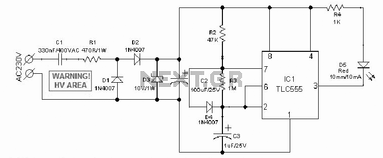
An AC mains operated single LED flasher circuit is designed using the widely used CMOS timer chip TLC555. The entire circuit is powered directly by the grid supply of 230VAC through a capacitive potential divider and associated components.
This LED flasher...

LED Dimmer Lighting
A dimmer for individual LED bulbs. LEDs (light emitting diodes) are very sensitive components; exceeding their rated current or voltage can drastically reduce their lifespan from over 50,000 hours to mere microseconds. LEDs are current-driven, meaning that the intensity of...