


Would this USB detection circuit work as expected

Description: When only the voltage regulator (VR) supplies power to the circuit, the microcontroller unit (MCU) will receive power from the +5V bus, while the FTDI chip will only receive VCCIO. At the midpoint of the voltage divider formed by resistors R10 and R11, a voltage of 0 is expected, which will prevent the MCU from detecting a USB connection on pin B. The inquiry is whether this setup will function as described or if there is a potential oversight. There is a concern regarding the safety and behavior of connecting only VCCIO to the FTDI chip.
In this circuit configuration, the voltage regulator (VR) serves as the primary power source, providing a stable +5V supply to the microcontroller unit (MCU). The FTDI chip, which is commonly used for USB to serial communication, requires both a power supply (VCC) and an I/O voltage (VCCIO) to operate correctly. In this scenario, the MCU is powered from the +5V bus, ensuring it has the necessary voltage for its operation.
The FTDI chip, however, is only connected to VCCIO, which is typically used to set the voltage level for the I/O pins of the chip. This setup raises concerns about the functionality of the FTDI chip since it may not receive the required power supply (VCC) to operate properly. The voltage divider formed by resistors R10 and R11 is intended to create a reference voltage, but if the midpoint voltage is 0V, it indicates that the divider is not functioning as expected, potentially leading to an inability for the MCU to detect the USB connection.
The primary concern is whether supplying only VCCIO to the FTDI chip could result in damage or unpredictable behavior. Many digital components, including the FTDI chip, require a proper power supply to function correctly. Operating the chip without VCC may lead to undefined states, which could cause erratic behavior or even permanent damage to the device. It is crucial to ensure that the FTDI chip is provided with the appropriate power supply alongside the I/O voltage to guarantee reliable operation and prevent any adverse effects on the circuit.
In conclusion, it is advisable to revise the circuit design to include a stable VCC supply for the FTDI chip in addition to VCCIO to ensure proper functionality and avoid potential damage.When ONLY VR will supply power to circuit, then MCU again will get power from +5V bus, but FTDI will ONLY get VCCIO. On middle of voltage divider R10/R11 I expect there will be 0 and MCU will not detect USB connection on (B).
The question is - would it work the way I described or I missed something My concern is it ok to hook up only VCCIO to FTDI Would it damage or lead to unknown behavior
In this circuit configuration, the voltage regulator (VR) serves as the primary power source, providing a stable +5V supply to the microcontroller unit (MCU). The FTDI chip, which is commonly used for USB to serial communication, requires both a power supply (VCC) and an I/O voltage (VCCIO) to operate correctly. In this scenario, the MCU is powered from the +5V bus, ensuring it has the necessary voltage for its operation.
The FTDI chip, however, is only connected to VCCIO, which is typically used to set the voltage level for the I/O pins of the chip. This setup raises concerns about the functionality of the FTDI chip since it may not receive the required power supply (VCC) to operate properly. The voltage divider formed by resistors R10 and R11 is intended to create a reference voltage, but if the midpoint voltage is 0V, it indicates that the divider is not functioning as expected, potentially leading to an inability for the MCU to detect the USB connection.
The primary concern is whether supplying only VCCIO to the FTDI chip could result in damage or unpredictable behavior. Many digital components, including the FTDI chip, require a proper power supply to function correctly. Operating the chip without VCC may lead to undefined states, which could cause erratic behavior or even permanent damage to the device. It is crucial to ensure that the FTDI chip is provided with the appropriate power supply alongside the I/O voltage to guarantee reliable operation and prevent any adverse effects on the circuit.
In conclusion, it is advisable to revise the circuit design to include a stable VCC supply for the FTDI chip in addition to VCCIO to ensure proper functionality and avoid potential damage.When ONLY VR will supply power to circuit, then MCU again will get power from +5V bus, but FTDI will ONLY get VCCIO. On middle of voltage divider R10/R11 I expect there will be 0 and MCU will not detect USB connection on (B).
The question is - would it work the way I described or I missed something My concern is it ok to hook up only VCCIO to FTDI Would it damage or lead to unknown behavior

Industrial fuel oil furnace controller circuit diagram 2
The industrial fuel oil furnace controller circuit consists of a power supply circuit, a testing and ignition control circuit, and a control implementation circuit, as illustrated in the accompanying diagram. The power supply circuit includes a step-down capacitor (C6), a...

A typical DVD switching power supply circuit
A typical DVD switching power supply circuit is shown in the standby power supply circuit of digital products. It utilizes a switching power supply structure, with the oscillation switch IC EA1623 providing oscillation pulses to the transformer. The secondary output...

Sanyo 83P switching power supply circuit diagram
Oscillation: The positive terminal voltage of C310 is approximately 300V. The resistors R311 and R312 are connected to the switch BG311 at the B pole, while the B301 winding via the switching transformer (4) and (6) is connected to the...

AMPLIFIER WITH FORCED EQUILIBRIUM ADAPTOR
Each power supply, whether linear or switching, operates in at least two modes: constant voltage (CV) and constant current (CC). The power supply can function in either mode, with the other serving as a protective mode for both the load...
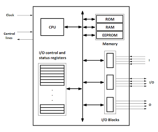
microcontrollers
Microcontrollers are integrated circuits that consist of a microprocessor along with additional units such as memory and input/output peripherals. This implementation allows for savings in time, space, and cost. Microcontrollers are commonly abbreviated as MCU (Microcontroller Unit), µC, or uC....

Switching power supply drive circuit
Driver circuit diagram: The primary function of the driver circuit is to serve as a variable width pulse width modulator output power amplifier, providing a drive signal to high voltage power switching devices. The driving circuit typically plays a role...

Evaluation Board For The Ad9834 Direct Digital Synthesizer
This document outlines the design of a low-cost 90 W flyback switching power supply intended for use in a multi-sync color monitor. To reduce screen interference caused by switching noise, the power supply can be automatically synchronized to the fixed...
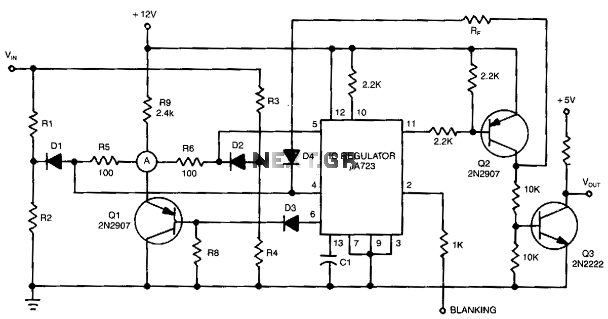
Window-detector
The detector circuit compares the output voltage of two separate voltage dividers with a fixed reference voltage. The resultant absolute error signal is amplified and converted to a logic signal that is TTL compatible.
The described detector circuit serves as a...

-15 V 1-A Regulated Power Supply
The supply receives -20 V from the rectifier/filter which is fed to the collector of the Darlington pnp pass transistor, a TIP105. The base drive to the TIP105 is supplied through resistor R5. The base of the TIP is driven...