


X10 Speech Recognition Interface pg4
#PIC 16F877
#speech recognition
#digital display
#LED
#comparator
#trigger
#microcontroller interface
#schematic

Description: The circuit is based on the PIC 16F877 microcontroller, as illustrated in figure 4. The digital display output of the speech recognition circuit connects directly to the pins of the microcontroller. An LED provides a trigger that informs the microcontroller when a word has been spoken. The LED output connects to one side of a comparator, while the other side connects to a voltage divider (Vref) composed of resistors R2 and R3, which creates a reference voltage for the comparator. When the LED blinks in the speech recognition circuit, it triggers the PIC 16F877 microcontroller on the X-10 interface to indicate that a word has been spoken. The microcontroller then reads the digital display output to determine if the word has been recognized (target word) or not (error code). If a target word is detected, it transmits the corresponding command and house code to the PL513 Power Line Interface. The following figure shows the prototype circuit built on solderless breadboards. The circuit is not critical, allowing for point-to-point wiring on standard breadboards. Additionally, a printed circuit board (PCB) and circuit kit are available through Images Scientific Instruments Inc., as detailed in the parts list. The PCB is displayed below, and the kit helps eliminate wiring errors while providing a polished appearance.
The circuit utilizes the PIC 16F877 microcontroller, which is a versatile and widely used component in embedded systems. This microcontroller features multiple I/O pins, enabling direct interfacing with various peripherals, including the digital display output from the speech recognition circuit. The LED serves as an essential visual indicator, signaling to the microcontroller that a speech input has been received.
The comparator's role is critical in this setup. It compares the voltage level from the LED output with the reference voltage generated by the voltage divider formed by resistors R2 and R3. The output from the comparator determines whether the microcontroller receives a high or low signal, indicating the presence of a spoken word.
Upon receiving a valid signal, the PIC 16F877 processes the digital display output to identify the spoken word. If the word matches a pre-defined target, the microcontroller sends the appropriate command and house code to the PL513 Power Line Interface, facilitating control over connected devices.
The circuit's design is user-friendly, allowing for flexibility in assembly. The use of solderless breadboards permits easy modifications and testing. The availability of a PCB kit further enhances the circuit's reliability by minimizing potential wiring errors and improving overall aesthetics.
This schematic effectively showcases the integration of speech recognition technology with microcontroller-based control systems, illustrating a practical application in home automation or similar fields. The detailed parts list and PCB design provide additional resources for individuals interested in replicating or building upon this project.The circuit is based on the PIC 16F877 microcontroller, see schematic in figure 4. The digital display output of the speech recognition circuit connects directly to the pins of the microcontroller. The LED in, provides a trigger that informs the microcontroller when a word has been spoken. The LED output connects to one side of a comparator. The o ther side connects to a voltage divider (Vref) made up of resistors R2 and R3 creating a reference voltage for the comparator. When the LED blinks on the speech recognition circuit it triggers the 16F877 microcontroller on the X-10 interface that a word has been spoken.
The microcontroller then reads the digital display output to determine if the word has been recognized (target word) or non-recognized (error code). If it reads a target word number it transmits the appropriate command and house code to the PL513 Power Line Interface.
The next figure shows my prototyped circuit I build on solderless breadboards. Nothing is critical about the circuit, you can use point to point wiring on standard breadboards if you like. The pc board and circuit is also available as a kit through my company, Images Scientific Instruments Inc.
, see parts list. The pc board is shown below. The kit eliminates wiring error and provides a finished appearance.
The circuit utilizes the PIC 16F877 microcontroller, which is a versatile and widely used component in embedded systems. This microcontroller features multiple I/O pins, enabling direct interfacing with various peripherals, including the digital display output from the speech recognition circuit. The LED serves as an essential visual indicator, signaling to the microcontroller that a speech input has been received.
The comparator's role is critical in this setup. It compares the voltage level from the LED output with the reference voltage generated by the voltage divider formed by resistors R2 and R3. The output from the comparator determines whether the microcontroller receives a high or low signal, indicating the presence of a spoken word.
Upon receiving a valid signal, the PIC 16F877 processes the digital display output to identify the spoken word. If the word matches a pre-defined target, the microcontroller sends the appropriate command and house code to the PL513 Power Line Interface, facilitating control over connected devices.
The circuit's design is user-friendly, allowing for flexibility in assembly. The use of solderless breadboards permits easy modifications and testing. The availability of a PCB kit further enhances the circuit's reliability by minimizing potential wiring errors and improving overall aesthetics.
This schematic effectively showcases the integration of speech recognition technology with microcontroller-based control systems, illustrating a practical application in home automation or similar fields. The detailed parts list and PCB design provide additional resources for individuals interested in replicating or building upon this project.The circuit is based on the PIC 16F877 microcontroller, see schematic in figure 4. The digital display output of the speech recognition circuit connects directly to the pins of the microcontroller. The LED in, provides a trigger that informs the microcontroller when a word has been spoken. The LED output connects to one side of a comparator. The o ther side connects to a voltage divider (Vref) made up of resistors R2 and R3 creating a reference voltage for the comparator. When the LED blinks on the speech recognition circuit it triggers the 16F877 microcontroller on the X-10 interface that a word has been spoken.
The microcontroller then reads the digital display output to determine if the word has been recognized (target word) or non-recognized (error code). If it reads a target word number it transmits the appropriate command and house code to the PL513 Power Line Interface.
The next figure shows my prototyped circuit I build on solderless breadboards. Nothing is critical about the circuit, you can use point to point wiring on standard breadboards if you like. The pc board and circuit is also available as a kit through my company, Images Scientific Instruments Inc.
, see parts list. The pc board is shown below. The kit eliminates wiring error and provides a finished appearance.

Knightrider lights for model cars
This simple circuit drives 6 LEDs in Knightrider scanner mode. Power consumption depends mainly on the type of LEDs used if you use a 7555 (555 CMOS version). More: Note that VDD and GND for the ICs are not shown...

508A microcontroller can deliver a maximum of 25mA
A typical device that requires less than 5v and draws less than 25mA is an LED. A LED must be supplied with an exact voltage for it to operate correctly. Because it requires LESS than 5v, a dropper resistor (current...

Pathway Lighting with LEDs
Simple pathway lighting that provides illumination for the path at night. Extension for the solar garden light. The toroid is bifilar wound.
The described circuit involves a solar-powered pathway lighting system designed to illuminate walkways during nighttime. This system utilizes...
white lights
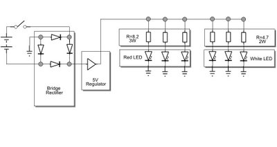
The white LEDs have varying voltage and current requirements, necessitating the use of different resistors. A parts list will be provided. The design concept is similar to previous iterations, but the white LEDs are configured differently due to their dedicated...

Christmas Star with LEDs
Using a PC parallel port to control external devices is a popular approach these days but I certainly couldn’t afford to tie up a PC for the few weeks leading up to Christmas just to flash a few LEDs! Not...

simple emergency led light circuit
This emergency LED light is simple, inexpensive, and easy to build. The circuit connects to the battery, activating when the main power source is unavailable, such as during brownouts. White LEDs turn on automatically. Initially, the output voltage from a...

Regulated LED Lamp
The LM317L and resistor act as a current regulator set to 40ma. Current flows from the battery through one pair of LEDs, through the regulator, through the other pair of LEDs, and back to the battery. The capacitor filters out...

Flickering LED Candle using Tiny45
There are many posts on Instructables detailing how to create a flickering LED candle. This version of the project requires several components.
The flickering LED candle project aims to simulate the warm glow and flicker of a real candle using electronic...

Comparator with variable hysteresis
An operational amplifier can be utilized as an effective device for analog comparator applications that necessitate two distinct trip points. The incorporation of a positive feedback network introduces a precise variable hysteresis into the conventional comparator switching action. This feedback...