


Atari 2600 CE
#Atari 2600
#retro gaming
#soldering
#modification
#hardware hack
#Classicgaming
#VCS
#DIY
#electronics repair

Description: Opening the VCS and applying a hot soldering iron may potentially damage the system. Neither Classicgaming nor Gamespy is liable for any harm caused to the user, the Atari console, or any associated property as a result of following these instructions. Begin by cutting six lengths of wire, ensuring ample length for flexibility. Solder these wires to the designated pins on the Stella Chip: 2, 5, 7, 8, 9, and 12. For all 2600 units, the Stella chip is located in a consistent position, typically among three large chips: two 40-pin DIPs and one 28-pin DIP at the center. The smaller center chip is the 6502 CPU, the chip nearest to the cartridge connector is the RIOT, and the largest chip farthest from the cartridge connector is the Stella. When examining the underside of the board, the pin soldered to a square pad is always pin 1, with subsequent pins counted away from it. If uncertainty arises, utilize the exposed metal areas where the RF shields were attached or solder directly to those locations, ensuring that the shields can be reattached. The potentiometers have three pins, but only two are needed; connect one of the two pins on the flat side and the single pin on the curved side. Connect wires from Stella pins 5 and 8 to the flat side of a pot, using one wire per pot (it is advisable to thread the wire through a hole next to the pot and solder them underneath). Twist together the three smaller wires along with the wires from Stella pins 2 and 9, and the wire from the center of the "V" RCA jack, then solder them together. An RCA cable should be connected from the "A" and "V" jacks to the audio and video inputs of a television or VCR (properly tuned to receive the signal, often labeled as AUX, INPUT1, or INPUT2). If color discrepancies occur, adjust the potentiometers individually with a small screwdriver until satisfactory results are achieved. Multiple games should be tested to ensure proper adjustment. If there is an absence of audio, video, or if the video is missing a color, inspect the connections made, as a loose wire from the Stella is usually the cause.
To create a functioning modification for the Atari 2600 console, it is essential to follow a systematic approach to ensure proper connectivity and functionality. The Stella chip, which is responsible for video output, requires specific pins to be connected to external components, such as potentiometers and RCA jacks.
First, identify the Stella chip and its position on the motherboard. The 2600's architecture typically places the Stella chip in a consistent location, facilitating easier identification. The soldering process involves connecting wires to the designated pins—2, 5, 7, 8, 9, and 12—ensuring that the solder joints are secure to prevent any future connectivity issues.
When preparing the potentiometers, it is important to recognize that only two of the three available pins will be utilized. The selection of pins should be made from the flat side of the potentiometer, where the two pins serve the same function, and the single pin on the curved side, which is crucial for the adjustment of video output levels. This configuration allows for fine-tuning of the signal to achieve optimal video quality.
Following the wiring connections, the RCA jacks must be properly integrated into the circuit. This involves soldering the twisted wire assembly from the Stella chip to the RCA jacks, ensuring that the audio and video signals are routed correctly to the television or VCR. The proper tuning of the receiving device is vital for the successful display of the video signal.
After completing the modifications, testing the setup with various games is recommended to ensure that the adjustments made to the potentiometers yield satisfactory results across different video outputs. If issues arise, troubleshooting should focus on the integrity of the solder joints and the connections made, as any loose wire can lead to loss of audio or video signals. This meticulous approach ensures that the Atari 2600 functions optimally after the modifications have been implemented.Since we will be opening your VCS and attacking it with a very hot soldering iron, it is possible that you will render your system dead. Neither I, Classicgaming, nor Gamespy are responsible for any damage done to yourself, your Atari, your family, your pets, your house, your neighborhod, or your precious Faberge egg collection that results either
directly or indirectly from you even reading these instructions, let alone attempting the modification described. Take six lengths of wire (give yourself plenty of wire, you can always cut them down), and solder them to the following pins on the Stella Chip: 2, 5, 7, 8, 9, and 12.
For all 2600 units, the Stella chip is basically in the same spot. Look for the big 3 chips, two of them are 40 pin DIPs and the center one is a 28 pin DIP (Dual Inline Pin). The Smaller, center chip is the 6502 CPU, the chip closest to the cartridge connector is the RIOT (most of the cartridge pins are connected to the RIOT, so it makes senese for them to be close).
and the big chip farthest from the cartridge connector is the Stella. Also notice that when you are looking at the underside of the board, one of the pins will be soldered to a square pad - that is always pin 1, and the other pins count away from it. If in doubt, use the exposed metal that the RF shields were attached to, or solder directly to those areas (make sure that you can still put the shields back on) The potentiometers (pots) have 3 pins, we only need two; there are two pins along the "flat" side - they do the same thing, we only need to connect one of them, and the single pin centered on the "curved" side.
Connect the wires from Stella 5 and 8 to the flat side of a pot, one wire per pot (it`s best to put the wire throuhg a hole next to the pot and solder them together underneath). Tightly twist together the three smaller wires and the wires from Stella 2 and 9, as well as the wire from the center of the "V" RCA jack and solder together.
Connect an RCA cable from the "A" and "V" jacks to the Audio and Video input of your TV or VCR (tuned properly to receive the signal - many TVs or VCRs call this AUX, INPUT1, or INPUT2). If the colors are off, adjust the pots, one at a time, with the small screwdriver until you are satisfied - you may want to try multiple games to make sure you have it adjusted correctly.
If you have do not have audio, video, or the video is missing a color, check the connections that you made, normally a wire is loose coming from the Stella.
To create a functioning modification for the Atari 2600 console, it is essential to follow a systematic approach to ensure proper connectivity and functionality. The Stella chip, which is responsible for video output, requires specific pins to be connected to external components, such as potentiometers and RCA jacks.
First, identify the Stella chip and its position on the motherboard. The 2600's architecture typically places the Stella chip in a consistent location, facilitating easier identification. The soldering process involves connecting wires to the designated pins—2, 5, 7, 8, 9, and 12—ensuring that the solder joints are secure to prevent any future connectivity issues.
When preparing the potentiometers, it is important to recognize that only two of the three available pins will be utilized. The selection of pins should be made from the flat side of the potentiometer, where the two pins serve the same function, and the single pin on the curved side, which is crucial for the adjustment of video output levels. This configuration allows for fine-tuning of the signal to achieve optimal video quality.
Following the wiring connections, the RCA jacks must be properly integrated into the circuit. This involves soldering the twisted wire assembly from the Stella chip to the RCA jacks, ensuring that the audio and video signals are routed correctly to the television or VCR. The proper tuning of the receiving device is vital for the successful display of the video signal.
After completing the modifications, testing the setup with various games is recommended to ensure that the adjustments made to the potentiometers yield satisfactory results across different video outputs. If issues arise, troubleshooting should focus on the integrity of the solder joints and the connections made, as any loose wire can lead to loss of audio or video signals. This meticulous approach ensures that the Atari 2600 functions optimally after the modifications have been implemented.Since we will be opening your VCS and attacking it with a very hot soldering iron, it is possible that you will render your system dead. Neither I, Classicgaming, nor Gamespy are responsible for any damage done to yourself, your Atari, your family, your pets, your house, your neighborhod, or your precious Faberge egg collection that results either
directly or indirectly from you even reading these instructions, let alone attempting the modification described. Take six lengths of wire (give yourself plenty of wire, you can always cut them down), and solder them to the following pins on the Stella Chip: 2, 5, 7, 8, 9, and 12.
For all 2600 units, the Stella chip is basically in the same spot. Look for the big 3 chips, two of them are 40 pin DIPs and the center one is a 28 pin DIP (Dual Inline Pin). The Smaller, center chip is the 6502 CPU, the chip closest to the cartridge connector is the RIOT (most of the cartridge pins are connected to the RIOT, so it makes senese for them to be close).
and the big chip farthest from the cartridge connector is the Stella. Also notice that when you are looking at the underside of the board, one of the pins will be soldered to a square pad - that is always pin 1, and the other pins count away from it. If in doubt, use the exposed metal that the RF shields were attached to, or solder directly to those areas (make sure that you can still put the shields back on) The potentiometers (pots) have 3 pins, we only need two; there are two pins along the "flat" side - they do the same thing, we only need to connect one of them, and the single pin centered on the "curved" side.
Connect the wires from Stella 5 and 8 to the flat side of a pot, one wire per pot (it`s best to put the wire throuhg a hole next to the pot and solder them together underneath). Tightly twist together the three smaller wires and the wires from Stella 2 and 9, as well as the wire from the center of the "V" RCA jack and solder together.
Connect an RCA cable from the "A" and "V" jacks to the Audio and Video input of your TV or VCR (tuned properly to receive the signal - many TVs or VCRs call this AUX, INPUT1, or INPUT2). If the colors are off, adjust the pots, one at a time, with the small screwdriver until you are satisfied - you may want to try multiple games to make sure you have it adjusted correctly.
If you have do not have audio, video, or the video is missing a color, check the connections that you made, normally a wire is loose coming from the Stella.

Crescendo ampilifier elektor1982
The Elector Crescendo was the first DIY amplifier that was not a kit. The design was sourced from the Elector magazines available at a local library.
The Elector Crescendo is an innovative audio amplifier designed for DIY enthusiasts. It features a...

turret diy
For maximum mini-security, this RC Tupperware Turret delivers a formidable deterrent against food theft. While it lacks motion sensors, potential food thieves will think twice before attempting to swipe baked goods. This 11-hour project, designed by Chris of PyroElectro, emphasizes...
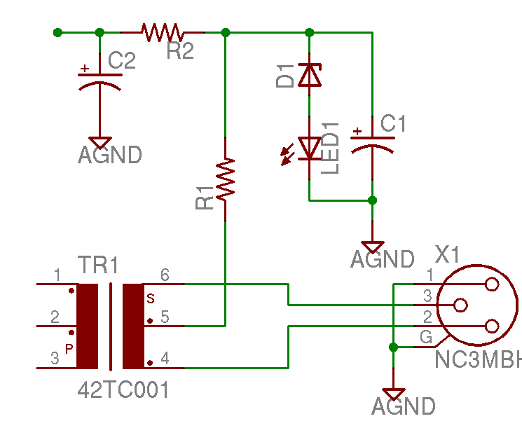
Help with a schematic please
A project is underway to construct the CountryHick DI as illustrated on DIYFactory, incorporating a few minor modifications. The final design aims to be a 1U unit with four inputs.
The CountryHick DI (Direct Injection) box is a crucial tool in...

Homemade Metal Detector Kit
A simple home project can quickly become problematic if it encounters electric cables, gas, or water pipes, or the central heating system. Using a metal detector allows one to check for metal objects within walls, ceilings, or floors beforehand. An...

MePADS
If you are considering building the Desert Ratt 2, it is advisable to read all the accompanying text, as it contains relevant construction details. Engaging with the comments and replies can also provide additional insights, as previous blog posts have...
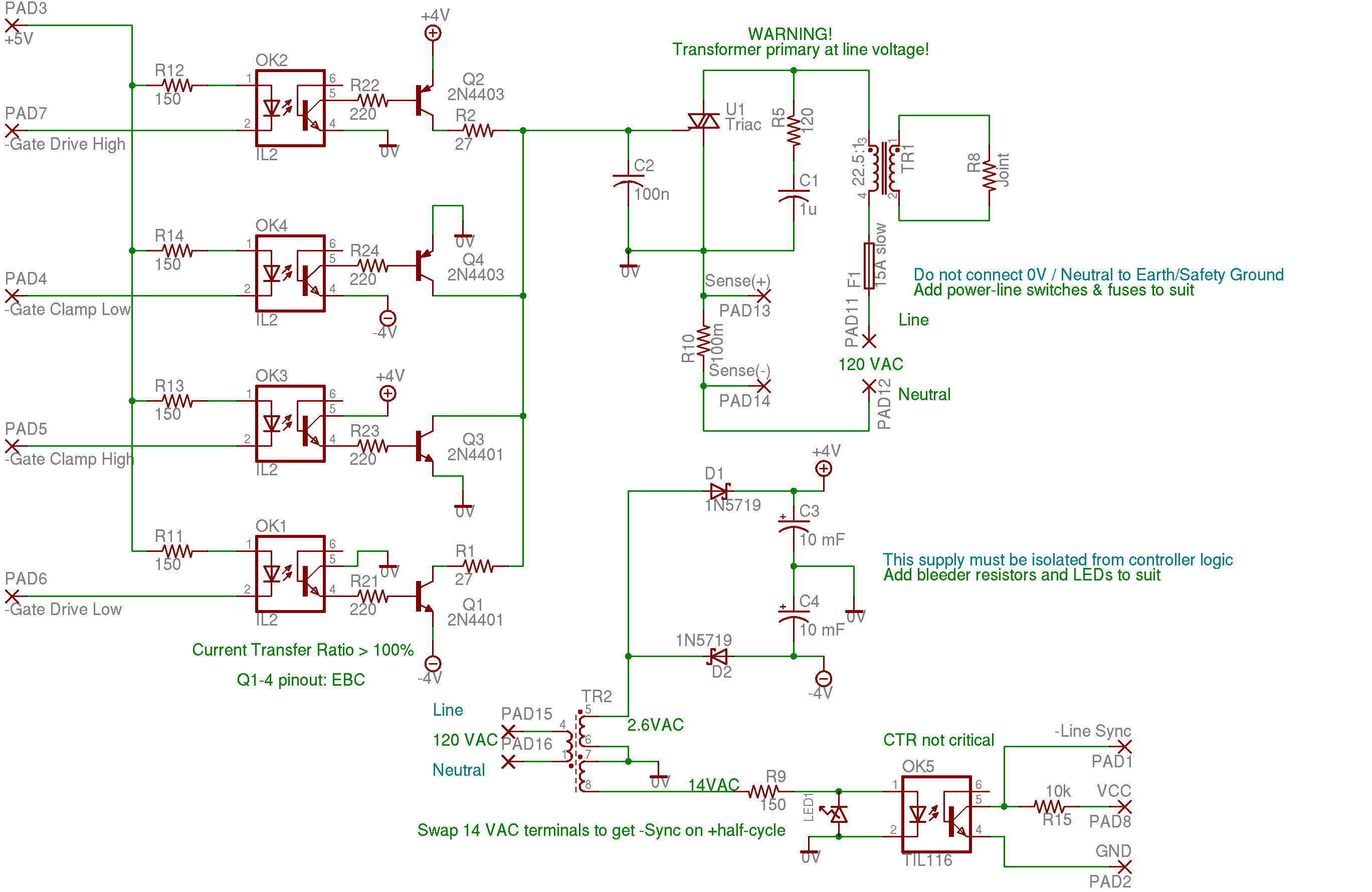
resistance soldering circuitry
None of this triggering circuitry is exactly what is desired, but it will provide a starting point in the right direction.
The triggering circuitry mentioned serves as a foundational element for various electronic applications, particularly in the realm of signal processing...

5 Minute Signal
For the past year and a half, a group based in Ann Arbor, Michigan, named GO-Tech has been formed, uniting individuals interested in creating projects using technology, such as hardware, software, metal, and wood. This initiative is referred to as...
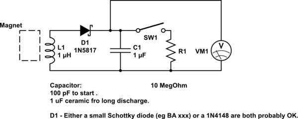
DIY kinetic energy harvester
A DIY kinetic energy harvester utilizing the electromagnetic method to generate electricity. The materials that will be used are currently known.
The project involves creating a kinetic energy harvester that converts mechanical energy from motion into electrical energy through electromagnetic induction....
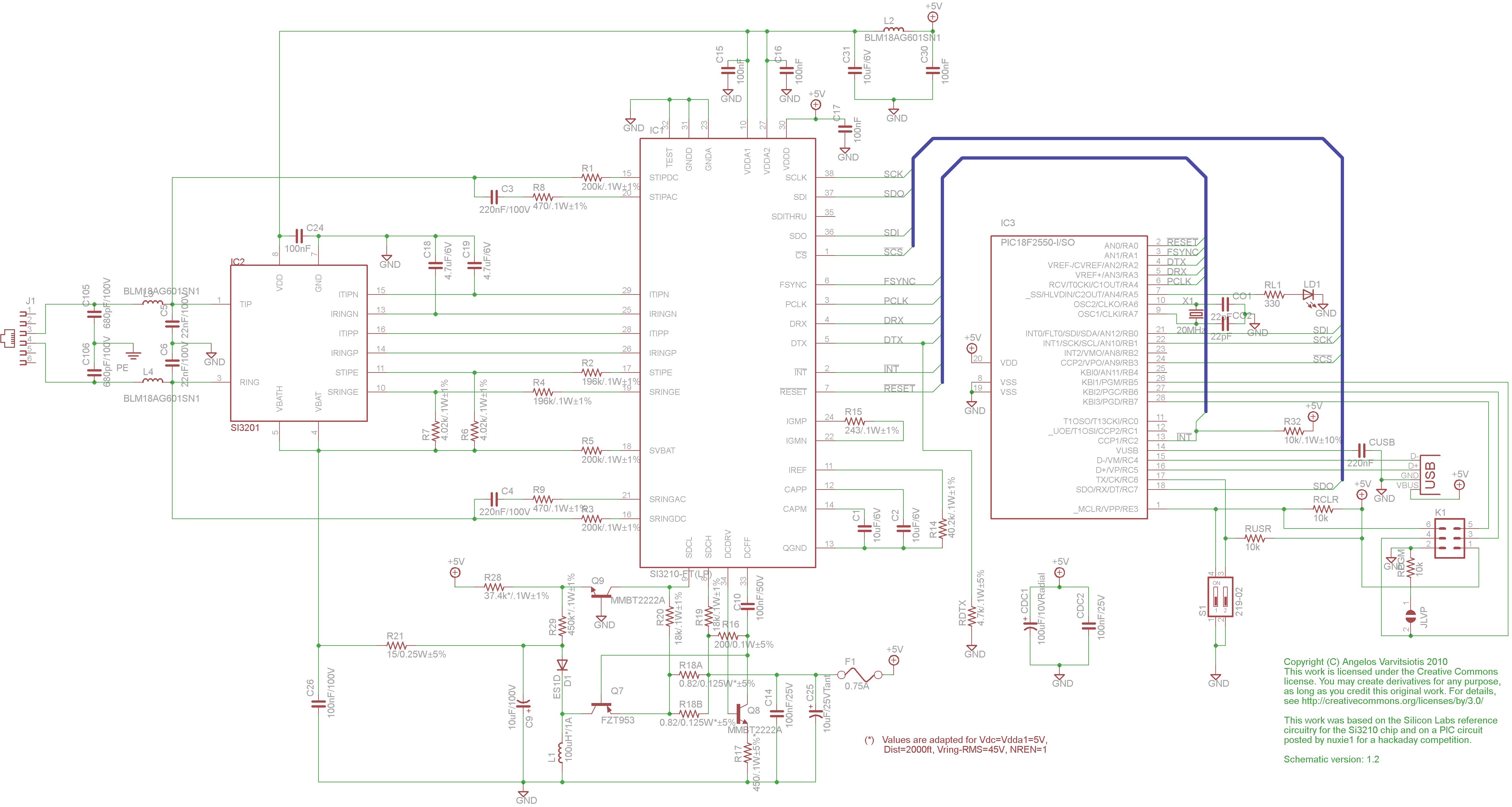
dyi setup and debugging guide
This page discusses the differences between assembled Open USB FXS dongle boards and DIY boards. While the assembled boards are fully tested and quality control approved, DIY boards may encounter various issues during assembly. Fortunately, most of these issues can...