


Birthday Heart circuit

Description: This is a birthday heart circuit. No much description is available but you can use your experienced imagination!
The birthday heart circuit is designed to create a visually appealing display, often used as a decorative element for celebrations. The circuit typically utilizes a series of light-emitting diodes (LEDs) arranged in the shape of a heart to provide illumination. The heart shape can be created using a printed circuit board (PCB) or a simple breadboard setup, depending on the complexity desired.
Power for the circuit is usually supplied by a low-voltage source, such as a battery or USB power supply, ensuring safety and ease of use. A common choice for the power supply is a 5V source, which is compatible with most standard LEDs.
To control the LEDs, a microcontroller or a simple timer circuit can be employed. For example, a 555 timer IC can be configured in astable mode to create a blinking effect, enhancing the visual appeal of the heart circuit. Alternatively, a microcontroller such as an Arduino can be programmed to control the timing and patterns of the LED illumination, allowing for more complex light displays such as fading or chasing effects.
The circuit may also include resistors to limit the current flowing through the LEDs, preventing damage and ensuring longevity. The value of the resistors can be calculated based on the forward voltage and current specifications of the chosen LEDs.
For enhanced functionality, additional components such as a switch can be integrated to turn the circuit on and off, or a potentiometer can be included to adjust the brightness of the LEDs. This flexibility allows for customization based on user preferences.
Overall, the birthday heart circuit serves as an engaging and festive electronic project, combining basic electronic components with creative design to celebrate special occasions.This is a birthday heart circuit. No much description is available but you can use your expirienced imagination! ;)
The birthday heart circuit is designed to create a visually appealing display, often used as a decorative element for celebrations. The circuit typically utilizes a series of light-emitting diodes (LEDs) arranged in the shape of a heart to provide illumination. The heart shape can be created using a printed circuit board (PCB) or a simple breadboard setup, depending on the complexity desired.
Power for the circuit is usually supplied by a low-voltage source, such as a battery or USB power supply, ensuring safety and ease of use. A common choice for the power supply is a 5V source, which is compatible with most standard LEDs.
To control the LEDs, a microcontroller or a simple timer circuit can be employed. For example, a 555 timer IC can be configured in astable mode to create a blinking effect, enhancing the visual appeal of the heart circuit. Alternatively, a microcontroller such as an Arduino can be programmed to control the timing and patterns of the LED illumination, allowing for more complex light displays such as fading or chasing effects.
The circuit may also include resistors to limit the current flowing through the LEDs, preventing damage and ensuring longevity. The value of the resistors can be calculated based on the forward voltage and current specifications of the chosen LEDs.
For enhanced functionality, additional components such as a switch can be integrated to turn the circuit on and off, or a potentiometer can be included to adjust the brightness of the LEDs. This flexibility allows for customization based on user preferences.
Overall, the birthday heart circuit serves as an engaging and festive electronic project, combining basic electronic components with creative design to celebrate special occasions.This is a birthday heart circuit. No much description is available but you can use your expirienced imagination! ;)
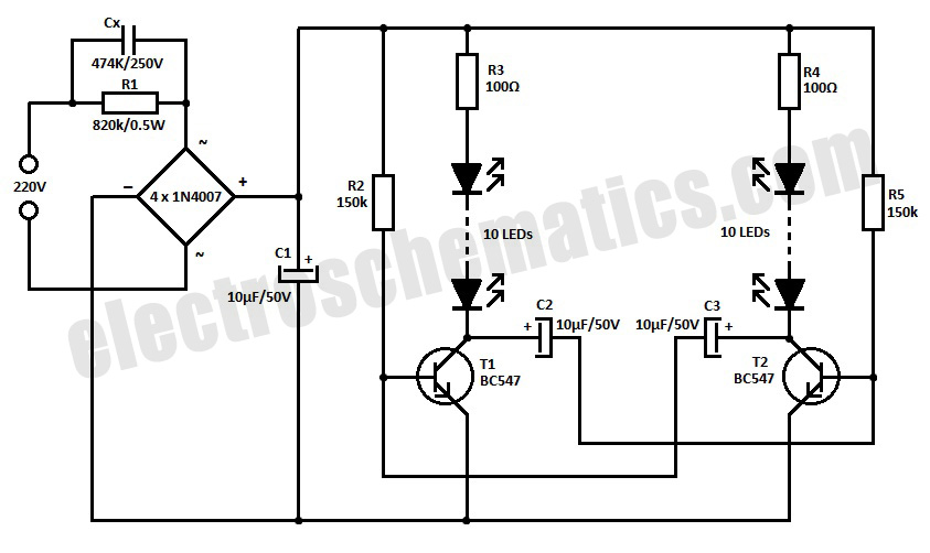
220V LED Blinker Circuit
This is a simple LED blinker or flasher designed for decorative purposes. The circuit features 20 high-brightness LEDs that flash alternately, creating a vibrant color display.
The LED blinker circuit typically consists of several key components including a microcontroller or timer...
Blue Blinky Joule circuit
Daylight shutoff; the schematic has been updated but is not shown here.
The daylight shutoff circuit is designed to automatically turn off lighting systems during daylight hours, thereby conserving energy and extending the lifespan of the lighting fixtures. Typically, this circuit...

Bonsai electronic circuit
The electronic components designed by conventional electronic bonsai create a sparkling and brilliant atmosphere in the living room, enhancing the joys and pleasures of life. The selection of components includes IC1 to IC4, which consist of two pairs of D...

Bicycle back Safety Lights
This circuit is designed to provide a clearly visible light using 13 high-efficiency flashing LEDs arranged in a pseudo-rotating order. Due to its low voltage, low battery drain operation, and compact size, the device is suitable for mounting on bicycles...

5 DOT LED LINEAR LEVEL METER DRIVER
The KA2284 is a monolithic integrated circuit designed for 5-dot LED level meter drives with a built-in rectifying amplifier. It is suitable for both AC and DC level meters, such as VU meters or signal meters.
The KA2284 integrated circuit is...

LED runner with 74LS163
This is a very simple circuit to build, just take note of the control pins on each IC, since both have enable inputs for counting or output, but once set you don't need to worry about them. From left to...

LED indication Integrated Circuits
The LB140 is depicted in Figure as a typical driver IC circuit for a five-digit LED level indicator. The BL1405 is commonly utilized in tape recorders for level indication.
The LB140 integrated circuit serves as a driver for five-digit LED displays,...

LED pulse width modulator
Early in the exploration of high-power LEDs, such as the Luxeon 1 and 3-watt devices, the potential of Pulse Width Modulation (PWM) techniques for LED modulation was considered. This method theoretically minimizes distortion by making the LED's "Current versus Luminous...

Comes with rechargeable lead-acid battery LED emergency light circuit diagram
The circuit diagram depicted in Figure 5 illustrates a system for charging a lead-acid battery using 220V AC power. The circuit employs a capacitor, buck converter, and diode rectifier for this purpose. A red LED indicates the charging status. When...