


Electronic games schematic circuit

Description: This document presents a principle circuit for electronic games. The main circuit operates in conjunction with the host through the reset button SB2, while the indicators VD1A-VD9A remain off. Prizes, for example, five, are determined by the number of players pointing to the Dot Award. The host activates switch S5, causing VD5B to illuminate. Subsequently, when the Dot Award button SB1 is pressed, IC3 is activated, playing "Kung Hei Fat Choi," a congratulatory message. Simultaneously, the oscillator circuit starts, generating a pulse signal that is sent to the CP pin of IC2, causing VD1A-VD9A to flash quickly in a clockwise manner. Upon releasing SB1, both IC1 and IC3 cease operation due to power disconnection. At this point, either one of VD1A-VD9A remains lit or they are all extinguished. If VD5A is illuminated and VD5B is in the same position, the point prize is successfully awarded.
The electronic circuit described operates as a game controller mechanism that interacts with players to provide feedback through visual indicators and audio signals. The circuit utilizes a combination of integrated circuits (ICs) and light-emitting diodes (LEDs) to manage user interactions and display results.
The main components include:
- **IC2**: This integrated circuit serves as a central processing unit, managing the reset function and controlling the overall operation of the circuit.
- **SB2**: A reset switch that initializes the circuit and ensures that the game starts from a known state.
- **VD1A-VD9A**: A series of nine LEDs that provide visual feedback to the players, indicating their progress and success within the game. These LEDs are designed to flash in a specific sequence to enhance the gaming experience.
- **S5**: A switch that activates the prize indicator. When pressed, it illuminates VD5B, signaling that a prize can be awarded.
- **SB1**: A button that, when pressed, triggers IC3 to play an audio congratulatory message while simultaneously starting the oscillator circuit.
- **IC3**: This integrated circuit is responsible for generating audio output, providing a congratulatory message to the players.
- **Oscillator Circuit**: This circuit generates pulse signals that control the flashing of the LEDs, creating a dynamic visual effect during gameplay.
The operation begins when players engage with the game, pressing SB2 to reset the circuit. The game state is indicated by the LEDs VD1A-VD9A, which remain off until the game is activated. Once the host activates S5, the prize indicator VD5B lights up, signaling the availability of a prize. Players then press SB1 to initiate the congratulatory message and the flashing sequence of the LEDs. The oscillator circuit produces rapid pulses, causing the LEDs to flash in a clockwise motion, enhancing the excitement of the game.
Upon releasing SB1, the power supply to IC1 and IC3 is cut off, halting their operations. At this moment, the state of VD1A-VD9A will either show one LED lit or all LEDs extinguished, depending on the game outcome. If both VD5A and VD5B are illuminated simultaneously, it confirms that the player has successfully achieved the point prize, concluding that round of the game. This circuit design exemplifies the integration of visual and auditory signals to create an engaging electronic gaming experience.Today, we share a principle circuit of electronic games. The main circuit in accordance with the host through the IC2 reset press SB2, VD1A-VD9A not light. Prizes (for example 5) Which position by the number of people pointing Dot Award, the host closing the switch S5 so VD5B shine. Then dot award presses SB1, IC3 energize play "Kung Hei Fat Choi" a congratulatory speech. At the same time start-up oscillator circuit, a pulse signal is applied to IC2 CP end, VD1A-VD9A clockwise quickly flashing. When you release the SB1, IC1, IC3 because the power supply is cut off and stop working. At this time, VD1A-VD9A only one is lit or completely extinguished. If you happen to be VD5A lit it and VD5B in the same position on the light emitting point prize success.
As shown below.
The electronic circuit described operates as a game controller mechanism that interacts with players to provide feedback through visual indicators and audio signals. The circuit utilizes a combination of integrated circuits (ICs) and light-emitting diodes (LEDs) to manage user interactions and display results.
The main components include:
- **IC2**: This integrated circuit serves as a central processing unit, managing the reset function and controlling the overall operation of the circuit.
- **SB2**: A reset switch that initializes the circuit and ensures that the game starts from a known state.
- **VD1A-VD9A**: A series of nine LEDs that provide visual feedback to the players, indicating their progress and success within the game. These LEDs are designed to flash in a specific sequence to enhance the gaming experience.
- **S5**: A switch that activates the prize indicator. When pressed, it illuminates VD5B, signaling that a prize can be awarded.
- **SB1**: A button that, when pressed, triggers IC3 to play an audio congratulatory message while simultaneously starting the oscillator circuit.
- **IC3**: This integrated circuit is responsible for generating audio output, providing a congratulatory message to the players.
- **Oscillator Circuit**: This circuit generates pulse signals that control the flashing of the LEDs, creating a dynamic visual effect during gameplay.
The operation begins when players engage with the game, pressing SB2 to reset the circuit. The game state is indicated by the LEDs VD1A-VD9A, which remain off until the game is activated. Once the host activates S5, the prize indicator VD5B lights up, signaling the availability of a prize. Players then press SB1 to initiate the congratulatory message and the flashing sequence of the LEDs. The oscillator circuit produces rapid pulses, causing the LEDs to flash in a clockwise motion, enhancing the excitement of the game.
Upon releasing SB1, the power supply to IC1 and IC3 is cut off, halting their operations. At this moment, the state of VD1A-VD9A will either show one LED lit or all LEDs extinguished, depending on the game outcome. If both VD5A and VD5B are illuminated simultaneously, it confirms that the player has successfully achieved the point prize, concluding that round of the game. This circuit design exemplifies the integration of visual and auditory signals to create an engaging electronic gaming experience.Today, we share a principle circuit of electronic games. The main circuit in accordance with the host through the IC2 reset press SB2, VD1A-VD9A not light. Prizes (for example 5) Which position by the number of people pointing Dot Award, the host closing the switch S5 so VD5B shine. Then dot award presses SB1, IC3 energize play "Kung Hei Fat Choi" a congratulatory speech. At the same time start-up oscillator circuit, a pulse signal is applied to IC2 CP end, VD1A-VD9A clockwise quickly flashing. When you release the SB1, IC1, IC3 because the power supply is cut off and stop working. At this time, VD1A-VD9A only one is lit or completely extinguished. If you happen to be VD5A lit it and VD5B in the same position on the light emitting point prize success.
As shown below.
Fine Control Super Bright LED Pulser
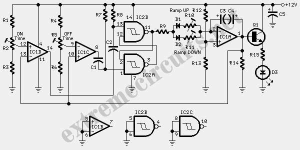
The circuit utilizes two white LEDs, with the second LED connected across the emitter of the transistor and the negative ground. It requires its own limiting resistor in series, similar to R15 and D3 in the circuit diagram. If standard...

The LED car voltmeter (2)
This document introduces an LED car voltmeter constructed using the op-amp LM312 and LED components. It is designed to display six voltage levels ranging from 10V to 15V, with each level representing a 1V increment. The working principle of the...

Ultra Bright LED Lamp
This ultra-bright white LED lamp operates on 230V AC with minimal power consumption. It is suitable for illuminating VU meters, SWR meters, and similar applications. The cost of ultra-bright LEDs available in the market ranges from Rs 8 to 15....

LED effects with ATTYNI2313
This project I made for my little daughter. It is 24 channel light illumination. The schematic is very simple 24 LEDs, 1 MCU and some additional components. The main principle is dynamic indication, which is usually implemented for control of...

Constant LED power circuit
An LED is usually a series resistor needed to ensure that the LED does not get too much power. The disadvantage of such resistance is that the current through the LED and thus the brightness changes as the voltage changes....

The power indicator circuit
The ACER PM02 MP4 machine features a voltage status indicator circuit. When power is supplied, a red LED illuminates, indicating that the device is powered on. Upon entering operational mode, a green LED lights up.
The voltage status indicator circuit serves...

Animated LED for Bike Turning Signal
The circuit below demonstrates how to animate a bike turning signal using LEDs. The bike turning signal will blink sequentially from the right side (D1) to the left side (D5).
This circuit utilizes a series of light-emitting diodes (LEDs) arranged to...

16 led46 led circuit combination
A series combination of 16 LEDs provides a luminance (lux) equivalent to a 12W bulb. However, if two series combinations of 23 LEDs are connected in parallel (totaling 46 LEDs), the output is equivalent to a 35W light bulb. Diode...

Incandescent LED Circuit
This circuit when used with a 555 timer will cause light emitting diodes to turn on and off more slowly. This will make the LEDs appear similar to incandescent lamps.
The described circuit utilizes a 555 timer IC configured in an...