


EMP Generator Schematic
#EMP
#generator
#flash circuits
#disposable cameras
#coil
#high voltage
#instructable
#DIY
#electronics project
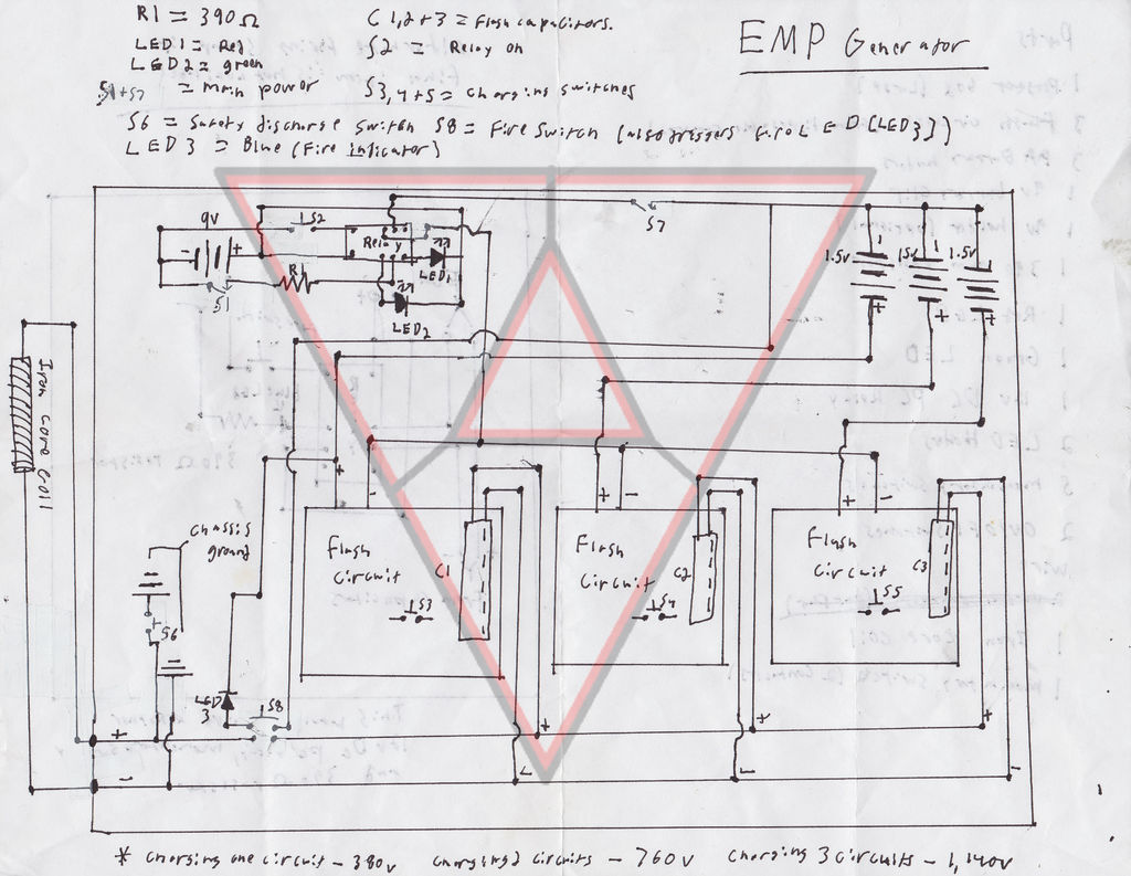
Description: These are plans for an EMP generator. It utilizes flash circuits from disposable cameras to power the coil. An instructable will be created soon.
The EMP generator design described involves utilizing the high-voltage flash circuits found in disposable cameras. These circuits are capable of generating a significant voltage, typically in the range of 300 to 400 volts, which is suitable for creating an electromagnetic pulse (EMP) effect. The basic components of the circuit include a capacitor, a transformer, and a discharge coil.
The disposable camera flash circuit operates by charging a capacitor through a low-voltage power supply, which is usually a small battery. Once the capacitor reaches its maximum charge, the circuit triggers the flash mechanism, discharging the stored energy through a transformer. This transformer steps up the voltage to a much higher level, which is then delivered to the discharge coil.
The discharge coil is a critical component of the EMP generator. It is designed to create a rapidly changing magnetic field when energized. The design of the coil, including the number of turns and the wire gauge, will significantly affect the efficiency and effectiveness of the EMP produced. A larger coil with more turns will typically generate a stronger magnetic field, leading to a more pronounced EMP effect.
Safety precautions are essential when working with high-voltage circuits, as the components can pose serious risks. Proper insulation, the use of protective gear, and adherence to safety guidelines are imperative when assembling and testing the EMP generator.
The instructable planned for this project will provide step-by-step guidance on the construction process, including a list of materials, circuit diagrams, and safety tips. This will enable individuals interested in replicating the design to do so while understanding the underlying principles and potential hazards associated with high-voltage electronics.These are my plans for an EMP Generator. It uses flash circuits from disposable cameras to power the coil. I plan to make an instructable of it soon..
The EMP generator design described involves utilizing the high-voltage flash circuits found in disposable cameras. These circuits are capable of generating a significant voltage, typically in the range of 300 to 400 volts, which is suitable for creating an electromagnetic pulse (EMP) effect. The basic components of the circuit include a capacitor, a transformer, and a discharge coil.
The disposable camera flash circuit operates by charging a capacitor through a low-voltage power supply, which is usually a small battery. Once the capacitor reaches its maximum charge, the circuit triggers the flash mechanism, discharging the stored energy through a transformer. This transformer steps up the voltage to a much higher level, which is then delivered to the discharge coil.
The discharge coil is a critical component of the EMP generator. It is designed to create a rapidly changing magnetic field when energized. The design of the coil, including the number of turns and the wire gauge, will significantly affect the efficiency and effectiveness of the EMP produced. A larger coil with more turns will typically generate a stronger magnetic field, leading to a more pronounced EMP effect.
Safety precautions are essential when working with high-voltage circuits, as the components can pose serious risks. Proper insulation, the use of protective gear, and adherence to safety guidelines are imperative when assembling and testing the EMP generator.
The instructable planned for this project will provide step-by-step guidance on the construction process, including a list of materials, circuit diagrams, and safety tips. This will enable individuals interested in replicating the design to do so while understanding the underlying principles and potential hazards associated with high-voltage electronics.These are my plans for an EMP Generator. It uses flash circuits from disposable cameras to power the coil. I plan to make an instructable of it soon..

turret diy
For maximum mini-security, this RC Tupperware Turret delivers a formidable deterrent against food theft. While it lacks motion sensors, potential food thieves will think twice before attempting to swipe baked goods. This 11-hour project, designed by Chris of PyroElectro, emphasizes...

HIGH VOLTAGE PULSE SUPPLY
This high-voltage pulse supply generates pulses up to 30 kV. Transistors Q1 and Q2 create a multivibrator in conjunction with peripheral components R1 through R6 and capacitors C1, C2, C3, C5, C6, and diode D2. Resistor R9 adjusts the pulse...
Glue stck torch
This project, developed around 2005, involves constructing a torch using a glue stick, which conveniently accommodates an AA battery within its plastic casing. To create a functional battery holder, contacts for both the positive and negative connections are necessary. The...

High Voltage Inverter
This is a simple high-voltage inverter circuit. It uses an NPN transistor type 2N3055. This circuit is designed to invert low voltage to high voltage.
The high-voltage inverter circuit utilizing the 2N3055 NPN transistor serves as an effective means to convert...
dyi setup and debugging guide
This page discusses the differences between assembled Open USB FXS dongle boards and DIY boards. While the assembled boards are fully tested and quality control approved, DIY boards may encounter various issues during assembly. Fortunately, most of these issues can...

Norton high voltage inverting amplifier
This circuit is an inverting amplifier with an output voltage swing from approximately 0 to +300 V. Any transistor can be utilized for Q1, as long as the breakdown voltage exceeds 300 V (since the full high voltage will be...

how to convert a 9v battery to 3.7v
A regulator circuit is needed for this DIY project. Familiarity with electronic components, circuitry, the use of a multitester, and a soldering iron is essential. The schematic diagram provided can accept an input voltage ranging from 6 to 24 volts...

Ultra high voltage generator
By repetitively charging and discharging a capacitor through the primary winding of an induction coil with high voltage, an ultra-high electromotive force (emf) is induced in the secondary winding. Switching is performed by a triac, which is triggered by a...

High Voltage Generation For Xenon Tube Applications
Power demand in portable designs can require, in specific applications, more than 1 A. A method involves paralleling two DC to DC converters on the same load instead of using a single higher current converter with a lower switching frequency....