


Homebuild Basic Plotter
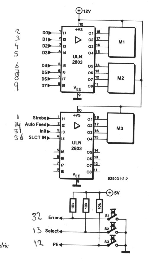
Description: A homebuilt basic plotter, engraver, vinyl cutter, and PCB driller utilizes a fundamental program to read HPGL files and control stepper motors connected to a parallel port.
This device serves multiple functions, including plotting, engraving, cutting vinyl, and drilling printed circuit boards (PCBs). The core of the system is a microcontroller or computer interface that processes HPGL (Hewlett-Packard Graphics Language) files, which are commonly used for vector graphics. The program interprets the commands in the HPGL file, translating them into precise movements for the stepper motors.
The stepper motors are essential components that provide the necessary movement for the tool head or cutting mechanism. They are controlled via a parallel port, which allows for direct communication between the computer and the motor drivers. The motor drivers receive signals from the computer and convert them into electrical pulses that drive the stepper motors with high accuracy and repeatability.
The mechanical structure of the plotter/engraver typically consists of a frame that supports the movement of the tool head along the X and Y axes, often using linear rails or rods to ensure smooth motion. The tool head can be equipped with various attachments depending on the desired function, such as a pen for plotting, a laser for engraving, a cutting blade for vinyl, or a drill bit for PCB drilling.
In addition to the mechanical and electrical components, the software plays a crucial role in ensuring the device operates correctly. The program must be capable of interpreting the HPGL commands accurately, managing the timing and sequence of motor movements, and providing feedback to the user regarding the status of the operation.
Overall, this homebuilt device represents a versatile and cost-effective solution for users interested in digital fabrication, allowing for the creation of detailed designs and prototypes in various materials.Homebuild Basic Plotter / Engraver / Vinyl-cutter / PCB-driller a basic program reads a HPGL file and controls stepper motors connected to parallel port..
This device serves multiple functions, including plotting, engraving, cutting vinyl, and drilling printed circuit boards (PCBs). The core of the system is a microcontroller or computer interface that processes HPGL (Hewlett-Packard Graphics Language) files, which are commonly used for vector graphics. The program interprets the commands in the HPGL file, translating them into precise movements for the stepper motors.
The stepper motors are essential components that provide the necessary movement for the tool head or cutting mechanism. They are controlled via a parallel port, which allows for direct communication between the computer and the motor drivers. The motor drivers receive signals from the computer and convert them into electrical pulses that drive the stepper motors with high accuracy and repeatability.
The mechanical structure of the plotter/engraver typically consists of a frame that supports the movement of the tool head along the X and Y axes, often using linear rails or rods to ensure smooth motion. The tool head can be equipped with various attachments depending on the desired function, such as a pen for plotting, a laser for engraving, a cutting blade for vinyl, or a drill bit for PCB drilling.
In addition to the mechanical and electrical components, the software plays a crucial role in ensuring the device operates correctly. The program must be capable of interpreting the HPGL commands accurately, managing the timing and sequence of motor movements, and providing feedback to the user regarding the status of the operation.
Overall, this homebuilt device represents a versatile and cost-effective solution for users interested in digital fabrication, allowing for the creation of detailed designs and prototypes in various materials.Homebuild Basic Plotter / Engraver / Vinyl-cutter / PCB-driller a basic program reads a HPGL file and controls stepper motors connected to parallel port..

SLA7070MPR 2-Phase Stepper Motor Unipolar Driver ICs
The SC1088 is a bipolar integrated circuit designed for use in mono portable and pocket radios. It is particularly beneficial when a minimal number of peripheral components, which are compact and cost-effective, is essential. The circuit features a frequency-locked loop...
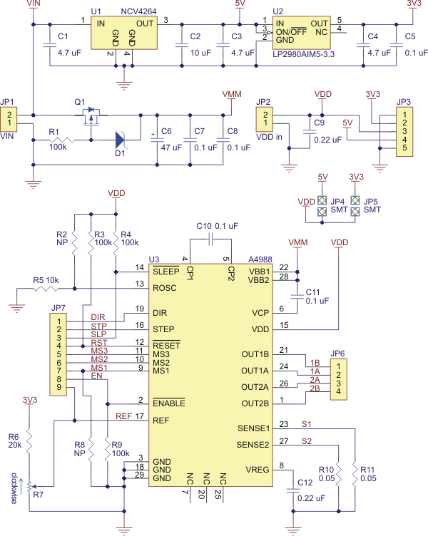
Stepper Motor Driver Carrier with Voltage Regulator
Best 1183 - A4988 Stepper Motor Driver Carrier with Voltage Regulator in Robot Italy. The A4988 stepper motor driver carrier with voltage regulators is a breakout board for Allegro's easy-to-use A4988 microstepping bipolar stepper motor driver. The board has two...

STEPPER MOTOR DRIVER
This circuit utilizes four IRF510 power FETs driven by a CMOS counter to produce the required two-phase drive quadrature. While integrated circuits (ICs) can perform this function, this method is beneficial for experimenters as it employs widely available components. The...

l297 stepper motor controller circuits
The L29 Stepper Motor Controller IC facilitates the control of four drive signals for two bipolar and four unipolar footfall motors in a microcomputer-controlled appliance. It allows for motor operation in half-step, full-step, and wave drive modes, utilizing switch-mode control...

Wireless Stepper Motor Control using Laser and IC555
Wireless stepper motor speed control project using a laser and IC555. This project provides insights into the fundamentals and circuit construction for controlling the speed of a wireless stepper motor utilizing a laser and the IC 555 timer.
The project centers...
DIY kinetic energy harvester
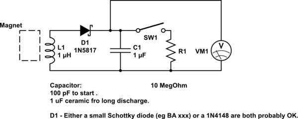
A DIY kinetic energy harvester utilizing the electromagnetic method to generate electricity. The materials that will be used are currently known.
The project involves creating a kinetic energy harvester that converts mechanical energy from motion into electrical energy through electromagnetic induction....

stepper ttl
The schematic illustrates the electronics needed to control a stepper motor. It primarily consists of three commonly available integrated circuits and four power transistors for complete motor control. Four PNP power transistors amplify the weak electronic signals into sufficient current...

Stepper Motor Controller
I found this circuit in my files. I don't know where it came from, but it looks like I photocopied it from somewhere years ago. I have been told that it came from "The Robot Builder's Bonanza", by Gordan McComb....

Driving Stepper
M1 is a stepper taken from an old disk drive. There are five pins, i.e., common, coil 1, 2, 3 and 4. Resistance measured between common pin and each coil is about 75 Ohms. Driving current for each coil is...