


hydraulic

Description: The hydraulic system comprises pump No. 8 installed on the gearbox, a dispenser, an oil tank, a hydraulic jack, and oil conduits. Oil flows from the tank through conduit No. 9, is drawn into pump No. 8, and is delivered to the dispenser via conduit No. 7. The dispenser, equipped with four valves, can direct oil either to the bottom of the jack (to raise the derrick) through conduit No. 2, to the top of the jack (to lower the derrick) via conduit No. 6, or back to the oil tank through conduit No. 3. The dispenser consists of a case secured to a bracket by bolts, with valves No. 10 and 11 located on the right side and valves No. 13 and 14 on the left side. A manual oil pump is included in the system to raise the derrick at a slight angle, allowing the cab to be thrown back in the event of engine failure. Oil from the pump enters a connecting branch, where a back valve with a spring moves the ball aside, leading to the connecting channel. Shutoff valves close the cross channels that connect the raising conduits and the top of the hydraulic jack. The cross channels contain orifices with valves, which are interconnected by a common link leading to the unloading line's connecting branch. Above the connecting channel is a safety valve, which consists of a ball and spring mechanism; when activated, it allows oil to flow into the low drain channel through various orifices. The double-step hydraulic jack, used for raising and lowering the mast, consists of a jacking pad, outer cylinder, and inner piston. The pistons are sealed with cups. The jacking pad is mounted on bearings, and the rod connects to the mast through a fork, roller, and eye. Oil is supplied to the lower room to raise the mast and to the upper room to lower it, with copper gaskets preventing oil leakage. A valve within the jacking pad regulates oil flow during the lowering process.
The hydraulic system operates through a series of interconnected components designed to manage the flow of hydraulic fluid effectively. The central pump, located on the gearbox, is responsible for generating the necessary pressure to move the oil through the system. The oil tank serves as a reservoir, ensuring a continuous supply of hydraulic fluid.
The dispenser plays a crucial role in directing the oil flow, utilizing multiple valves to control the movement of the hydraulic jack. The configuration allows for precise control of the derrick's position, enabling it to be raised or lowered as required. The manual pump serves as a backup mechanism, ensuring that the system can still function in the event of a power failure.
Safety features are integrated into the design, including the back valve with a spring mechanism and the safety valve, which prevents over-pressurization and potential damage to the system. The use of copper gaskets throughout the hydraulic jack assembly minimizes the risk of leaks, ensuring efficient operation.
The double-step hydraulic jack itself consists of a robust construction with a jacking pad that supports the entire assembly. The inner and outer cylinders house the pistons, which are designed to create a sealed environment, allowing for effective lifting and lowering of the mast. The incorporation of sealing cups further enhances the reliability of the jack by preventing fluid escape.
Overall, the hydraulic system's design emphasizes efficiency, safety, and reliability, making it suitable for demanding applications such as derrick operation. Each component has been meticulously designed to work in harmony, providing a robust solution for hydraulic lifting needs.The hydraulic system includes pump No. 8 (Drawing 10) installed on the gearbox, dispenser (1), oil tank (4), hydraulic jack (5) and oil conduits. From the tank oil moves along conduit (9), sucked in the pump (8) and gets into dispenser (1) via conduit (7).
The oil in the dispenser with four valves (10, 11, 13, 14) may be guided either to the jack b ottom (to raise the derrick) via conduit No. 2, or to the jack top (to lower the derrick) via conduit No. 6 or to the oil tank via conduit No. 3. The dispenser consists of the case fastened to the bracket by bolts. On the right side the case is equipped with valves No. 10 and 11; on the left side valves No. 13 and 14. The hydraulic system has manual oil pump (15); its function is to raise the derrick at slight angle so that to throw back the cab if the engine has broke down. From pump the oil gets into the connecting branch (back valve with spring (12) move the ball aside) and then to the connecting channel.
Shutoff valves (11 and 13) close cross channels that lead to the connecting branches of raising conduits and to the top of hydraulic jack. Cross channels have orifices with valves (10 and 14); rooms of these valves are interconnected by common link incoming to the connecting branch of the unloading line.
Over connecting channel there is a safety valve consisting of ball with spring; one end of the spring is inserted into the cage, the other one leans on the ball via guide through special plate. When the safety valve is active oil raises the ball and gets into the low drain channel through horizontal and vertical orifices.
The drain channel is under the rooms of valves No. 10 and 14. 1 - dispenser; 2, 6, 7, 9 - conduits; 3 - unloading line; 4 - oil tank; 5 hydraulic jack; 8 - pump; 10, 11, 13, 14 - valves; 12 - spring; 15 manual pump Double-step hydraulic jack (for raising and lowering the mast) consists of the following parts (Drawing 11): jacking pad (1), outer cylinder (4), inner piston (7). The pistons are sealed by cups (11 and 12). 1 - jacking pad; 2 - bearing; 3 connecting branch; 4 - cylinder; 5 - piston; 6 - inner cylinder; 7 - piston: 8 - roller; 9 - eye; 10 - fork; 11, 12 - cups; 13 - valve; 14 - connecting branch The jacking pad is mounted on the bearings (2).
The rod is connected with the mast through the fork (10), roller (8) and eye (9). The sealing between cylinder bottom and the jacking pad is copper. To raise the mast the oil is supplied to the lower room through the connecting branch (14); to lower the mast to the upper room through the connecting branch (3). To prevent oil leakage the copper gaskets are inserted in the pivot recesses; the gaskets are compressed by connecting branches when screwing.
In the jacking pad (1) there is a valve (13) which decreases the oil flow to the front pad when the derrick is being lowered. Oil is supplied to the upper and lower cylinder rooms through the oil devices mounted in the pad (1) pivot.
To prevent oil leakage the copper gaskets are inserted in the pivot recesses; the gaskets are compressed by connecting branches (3 and 14) when screwing. Threaded head of the jacking pad is equipped with the valve which serves as the safety device when lowering the mast.
The hydraulic system operates through a series of interconnected components designed to manage the flow of hydraulic fluid effectively. The central pump, located on the gearbox, is responsible for generating the necessary pressure to move the oil through the system. The oil tank serves as a reservoir, ensuring a continuous supply of hydraulic fluid.
The dispenser plays a crucial role in directing the oil flow, utilizing multiple valves to control the movement of the hydraulic jack. The configuration allows for precise control of the derrick's position, enabling it to be raised or lowered as required. The manual pump serves as a backup mechanism, ensuring that the system can still function in the event of a power failure.
Safety features are integrated into the design, including the back valve with a spring mechanism and the safety valve, which prevents over-pressurization and potential damage to the system. The use of copper gaskets throughout the hydraulic jack assembly minimizes the risk of leaks, ensuring efficient operation.
The double-step hydraulic jack itself consists of a robust construction with a jacking pad that supports the entire assembly. The inner and outer cylinders house the pistons, which are designed to create a sealed environment, allowing for effective lifting and lowering of the mast. The incorporation of sealing cups further enhances the reliability of the jack by preventing fluid escape.
Overall, the hydraulic system's design emphasizes efficiency, safety, and reliability, making it suitable for demanding applications such as derrick operation. Each component has been meticulously designed to work in harmony, providing a robust solution for hydraulic lifting needs.The hydraulic system includes pump No. 8 (Drawing 10) installed on the gearbox, dispenser (1), oil tank (4), hydraulic jack (5) and oil conduits. From the tank oil moves along conduit (9), sucked in the pump (8) and gets into dispenser (1) via conduit (7).
The oil in the dispenser with four valves (10, 11, 13, 14) may be guided either to the jack b ottom (to raise the derrick) via conduit No. 2, or to the jack top (to lower the derrick) via conduit No. 6 or to the oil tank via conduit No. 3. The dispenser consists of the case fastened to the bracket by bolts. On the right side the case is equipped with valves No. 10 and 11; on the left side valves No. 13 and 14. The hydraulic system has manual oil pump (15); its function is to raise the derrick at slight angle so that to throw back the cab if the engine has broke down. From pump the oil gets into the connecting branch (back valve with spring (12) move the ball aside) and then to the connecting channel.
Shutoff valves (11 and 13) close cross channels that lead to the connecting branches of raising conduits and to the top of hydraulic jack. Cross channels have orifices with valves (10 and 14); rooms of these valves are interconnected by common link incoming to the connecting branch of the unloading line.
Over connecting channel there is a safety valve consisting of ball with spring; one end of the spring is inserted into the cage, the other one leans on the ball via guide through special plate. When the safety valve is active oil raises the ball and gets into the low drain channel through horizontal and vertical orifices.
The drain channel is under the rooms of valves No. 10 and 14. 1 - dispenser; 2, 6, 7, 9 - conduits; 3 - unloading line; 4 - oil tank; 5 hydraulic jack; 8 - pump; 10, 11, 13, 14 - valves; 12 - spring; 15 manual pump Double-step hydraulic jack (for raising and lowering the mast) consists of the following parts (Drawing 11): jacking pad (1), outer cylinder (4), inner piston (7). The pistons are sealed by cups (11 and 12). 1 - jacking pad; 2 - bearing; 3 connecting branch; 4 - cylinder; 5 - piston; 6 - inner cylinder; 7 - piston: 8 - roller; 9 - eye; 10 - fork; 11, 12 - cups; 13 - valve; 14 - connecting branch The jacking pad is mounted on the bearings (2).
The rod is connected with the mast through the fork (10), roller (8) and eye (9). The sealing between cylinder bottom and the jacking pad is copper. To raise the mast the oil is supplied to the lower room through the connecting branch (14); to lower the mast to the upper room through the connecting branch (3). To prevent oil leakage the copper gaskets are inserted in the pivot recesses; the gaskets are compressed by connecting branches when screwing.
In the jacking pad (1) there is a valve (13) which decreases the oil flow to the front pad when the derrick is being lowered. Oil is supplied to the upper and lower cylinder rooms through the oil devices mounted in the pad (1) pivot.
To prevent oil leakage the copper gaskets are inserted in the pivot recesses; the gaskets are compressed by connecting branches (3 and 14) when screwing. Threaded head of the jacking pad is equipped with the valve which serves as the safety device when lowering the mast.
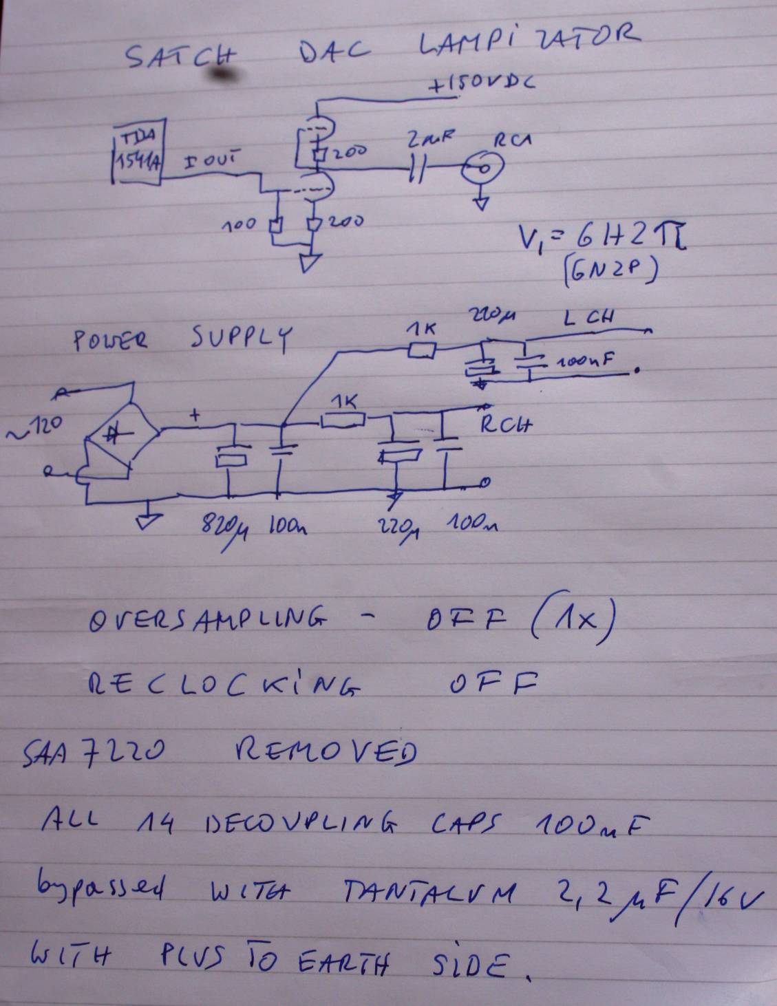
valves to replace opamps in cd player
Originally posted by ide2003, the message suggests that if one wishes to avoid using an operational amplifier (op-amp) entirely, it is highly recommended to consider ECDesign.
The mention of avoiding op-amps in circuit design indicates a preference for alternative methods of...

A hydraulic circuit diagram showing
The circuit diagram illustrates how an oil pressure sensor is transformed into a variable resistor, denoted as Rt. Variations in Rt lead to changes in the biasing of each transistor, which in turn controls three LEDs (red, yellow, and green)...

Hydraulic system
A hydraulic or hydrostatic drive system, also known as hydraulic power transmission, utilizes pressurized hydraulic fluid to drive machinery. The term hydrostatic refers to energy transfer through flow and pressure rather than the kinetic energy of the flow. This system...

Valves structure operation and use
The first television set observed in a household around 1950 was constructed from a kit by the father of the narrator. It was housed in a box and featured a single channel, BBC, broadcasting at 45 MHz. Despite the low-quality...

Mitsubishi: I am putting a hydraulic thumb on my excavator heads
The excavator is a Mitsubishi MS280. The issue at hand is uncertainty regarding the excitation of the pump. The intention is to install an electronic proportional control valve in the machine. The levers are connected via mechanical linkage to what...