


Logochip Creative Works
#Logochip
#Arduino
#DIY
#electronics
#prototyping
#cost-effective
#microcontroller
#hobbyist
#creative projects
#circuit design

Description: The processes of reducing a set of objects or functions to their lowest common denominator can be quite significant. A motivation for this approach is the desire to avoid the cost of purchasing an Arduino Decimila for every new project. Understanding the importance of designing a versatile and budget-friendly microcontroller system is essential. The microcontroller at the core of this system is the Atmel ATmega168-20PU, which costs approximately $4.00. Programming the bootloader into the Atmel chip requires a programming device, such as a USBtinyISP, which can be borrowed from a friend or purchased if multiple clones are planned. A stable 5-volt power supply is necessary for the chip, and the LM7805 voltage regulator, along with a couple of small capacitors (approximately $0.50), is recommended to ensure proper voltage regulation. For projects that already have a 5-volt source, such as an old computer power supply, that can be used, or a set of four rechargeable AA or AAA batteries can be employed for portable applications.
To keep the microcontroller operational, a 16 MHz crystal resonator (costing around $0.40) is required for clocking, which is suitable for serial communications between the Arduino and a computer. A 10,000-ohm resistor (costing about $0.02) is also necessary to pull the reset pin high, preventing the Arduino from entering sleep mode. When programming, the reset pin is activated to signal the Arduino to receive new data. The Arduino clone circuit includes a CD40106 inverter chip, which, along with a couple of resistors and capacitors, conditions the signals during programming. The Arduino communicates through three essential lines: RXD for receiving data, TXD for transmitting data, and DTR for data terminal ready, which resets the Arduino for new programming.
For wireless projects using the Logochip, an IR Receiver Module (Radioshack 276-640) can receive signals from an IR LED oscillating at 38 kHz. The Logochip can produce this 38 kHz signal and modulate it easily through software. The schematic illustrates the Logochip circuit on the left and the IR transmit and receive circuits on the right. The transmission involves two transistors, with one driving the LED by producing a 38 kHz square wave from the timer output. The other transistor controls the LED based on the transmit pin's signal. The receiver module connects directly to the 5-volt supply and outputs the signal to the RX pin.
Additionally, a memory chip can be connected to the Logochip using an I2C interface, allowing data retention when the power is off. This setup is straightforward and inexpensive. A suggestion for managing multiple Logochips involves utilizing the built-in serial communication ports. The master device's program differs slightly from the slaves, as the latter must wait for the master's command to communicate. The software allows for efficient energy regulation, using techniques like PWM to control devices without excessive energy loss. By pulsing the power supply, devices can operate effectively at higher voltages while managing energy consumption efficiently.
This comprehensive overview provides a foundation for building versatile and cost-effective electronic projects using the Logochip and associated components.There is something to be said for the processes of reducing a set of objects or functions down to their lowest common denominator but I think what has really driven me to do this is I am too cheap to go out and buy an Arduino Decemila every time I want to built a new project. But really after doing quite a bit of business with the Logochips I thin k I understand how important it is to try to design The little engine that could do almost anything on a budget. This could be cool, and time will tell what all can be done with it. First there is the microcontroller, the brain, the Atmel ATmega168-20PU(costs about $4. 00). I should mention here that you need a way to program the bootloader into the Atmel chip. If you have a friend like Keith who will lend you his USBtinyISP and an Arduino Decemila it makes it real easy.
Other wise buying one of each might be good if you plan to make a lot of clones. Next you need to provide the chip with a good 5 volt supply. I suggest the LM7805 and a couple of small capacitors(costs about 50 cents) to regulate just about any voltage down to a nice safe 5 volts for the microcontroller. If you are making a project that already has a 5 volt supply like an oldcomputer power supply you can use that or a set of 4 rechargeable batteries (AA or AAA) works well for those portable projects.
Now the brain needs a clock to keep it on time. That would be this, 16 megahertz crystal resonator (costs about 40 cents). Your probably reading this post on a laptop or desktop computer that is screaming along at 1 or 2 gigahertz well, just slow down, take it easy, 16MHz is just the right speed for the serial communications between theArduino and your computer. One more thing. The brain has a tendency to fall asleep. You`ll need a 10, 000 ohm resistor (cost 2 cents) to pull the reset pin up to 5 volts and keep theArduino running.
When you download a program from your computer this reset pin gets kicked to tell the Arduino HEY I got somthin for ya . OK now in the picture here the Arduino clone circuit described above is on the left side and on the right side is another small chip CD40106 which is called an inverter.
It and a couple of resistors and a capacitor will condition the signals to and from your computer when your downloading a program to the Arduino. When your done programming you can remove these parts and the Arduino will run by itself. There are three lines of communication that the Arduino needs to successfully download a program, RXD receive data, TXD transmit data, and DTR data terminal ready.
The DTR is the one that kicks the reset pin and makes the Arduinogulp down a new program. When ever I find an easy way to do something I just have to make a record of it. There are some projects where you might want to do something wireless with the Logochip. This little circuit makes it pretty easy. First an explination of the Radioshack 276-640, the IR Receiver Module. It will receive signals from an IR(940nm) LED that is oscillating at 38killoherts. So if we want to send a series of 1 ²s and 0 ²s we modulate this 38KHz signal on and off. Fortunately the Logochip can produce the 38KHz signal and modulate it with very little effort from the software. G‚ We`re going to set up the internal timer module to produce the signal and set up the serial UART to modulate it.
So here let`s look at the schematic. This schematic shows the Logochip circuit to the left and the IR transmit and receive circuits to the right. There are two transistors involved in the in the transmit. The one that drives the LED is driven by the timer output PORTC bit 2 which is producing a 38KHz square wave.
But most of the time it is being held off by the other transistor which is being driven by the transmit pin (TX) PORTC bit 6. Now when you tell the serial port to transmit an 8 bit byte the serial data comes out of the TX pin and modulates the 38KHz signal on and off to the LED.
On the receiver side (this is really easy) the Radioshack part is simply hooked up to the 5 volt power and ground and the output signal runs right into the receiver input (RX) PORTC bit 7. I put a resistor to ground just in case the output drifts. That`s it. Here`s a picture of my bread board. IRlogoProtoBoard G‚. The transmit LED and the receiver module are pointing straight up and I just help my hand above it to reflect the signal back.
I can`t wait to use it in something. Using the lab notes from Prof. Robbie Berg I hooked up a memory chip to a Logochip using an I2C interface. So if somebody would want their Logochip to remember a bunch of numbers like a data pattern or say an audio track this could help. It could also be helpful if you wanted to use another device that had an Io called 2 WIRE ) interface.
Memory is saved when the power is off too. The PDF formatting of his lab notes kind of screwed the line feeds so I tried to tidy things up. But itG ‚¬ s real easy to hook up. The part only costs a buck. You can paste this code in, load, and go. Might be a good thing to put in the wiki. This is in response to a previous error and also to make sure that parallel data lines to multiple LCD modules would work. I haven`t built the whole circuit but enough to conferm that it will work. Earlier I posted a schematic if a single line LCD module that had pin 3 grounded and it should have been tied high.
Here`s a picture ofG‚what I wired up: I know it sounds awful in this day and age to be using slaves but Logochips don`t really mind that much. There are a couple of groups that are considering multiple Logochips and here is a suggestion of how that can be done.
G‚ You can do something really easy by using the built in serial comm ports (portc 6 and portc 7). Here`s a brief schematic. The program that goes in the master is slightly different than the program in the slaves in that the slaves have to keep their mouths shout until spoken to by the master otherwise the master won`t know which slave is doing the talking. So here`s the Logochip software programs. What it allows us to do is regulate the flow of energy with out wasting so much of it. In the early days if you had a 12 volt battery and you wanted to drive a 6 volt lamp you could use a transistor to regulate the voltage down to 6 volts but half of the energy was wasted as heat in the transistor.
PWM uses the adveatage of time. A 6 volt light buld or a motor or many other devices can actually run at 12 volts just not for a long time. So we take advantage of that by pulsing. For instance, having the lamp on for 1/2 of a second and then off for 1/2 of a second would be like delivering 6 volts for one second.
Of course you could call that blinking but if you speed that up about 100 times and do it at a frequency of 1nother circuit.
To keep the microcontroller operational, a 16 MHz crystal resonator (costing around $0.40) is required for clocking, which is suitable for serial communications between the Arduino and a computer. A 10,000-ohm resistor (costing about $0.02) is also necessary to pull the reset pin high, preventing the Arduino from entering sleep mode. When programming, the reset pin is activated to signal the Arduino to receive new data. The Arduino clone circuit includes a CD40106 inverter chip, which, along with a couple of resistors and capacitors, conditions the signals during programming. The Arduino communicates through three essential lines: RXD for receiving data, TXD for transmitting data, and DTR for data terminal ready, which resets the Arduino for new programming.
For wireless projects using the Logochip, an IR Receiver Module (Radioshack 276-640) can receive signals from an IR LED oscillating at 38 kHz. The Logochip can produce this 38 kHz signal and modulate it easily through software. The schematic illustrates the Logochip circuit on the left and the IR transmit and receive circuits on the right. The transmission involves two transistors, with one driving the LED by producing a 38 kHz square wave from the timer output. The other transistor controls the LED based on the transmit pin's signal. The receiver module connects directly to the 5-volt supply and outputs the signal to the RX pin.
Additionally, a memory chip can be connected to the Logochip using an I2C interface, allowing data retention when the power is off. This setup is straightforward and inexpensive. A suggestion for managing multiple Logochips involves utilizing the built-in serial communication ports. The master device's program differs slightly from the slaves, as the latter must wait for the master's command to communicate. The software allows for efficient energy regulation, using techniques like PWM to control devices without excessive energy loss. By pulsing the power supply, devices can operate effectively at higher voltages while managing energy consumption efficiently.
This comprehensive overview provides a foundation for building versatile and cost-effective electronic projects using the Logochip and associated components.There is something to be said for the processes of reducing a set of objects or functions down to their lowest common denominator but I think what has really driven me to do this is I am too cheap to go out and buy an Arduino Decemila every time I want to built a new project. But really after doing quite a bit of business with the Logochips I thin k I understand how important it is to try to design The little engine that could do almost anything on a budget. This could be cool, and time will tell what all can be done with it. First there is the microcontroller, the brain, the Atmel ATmega168-20PU(costs about $4. 00). I should mention here that you need a way to program the bootloader into the Atmel chip. If you have a friend like Keith who will lend you his USBtinyISP and an Arduino Decemila it makes it real easy.
Other wise buying one of each might be good if you plan to make a lot of clones. Next you need to provide the chip with a good 5 volt supply. I suggest the LM7805 and a couple of small capacitors(costs about 50 cents) to regulate just about any voltage down to a nice safe 5 volts for the microcontroller. If you are making a project that already has a 5 volt supply like an oldcomputer power supply you can use that or a set of 4 rechargeable batteries (AA or AAA) works well for those portable projects.
Now the brain needs a clock to keep it on time. That would be this, 16 megahertz crystal resonator (costs about 40 cents). Your probably reading this post on a laptop or desktop computer that is screaming along at 1 or 2 gigahertz well, just slow down, take it easy, 16MHz is just the right speed for the serial communications between theArduino and your computer. One more thing. The brain has a tendency to fall asleep. You`ll need a 10, 000 ohm resistor (cost 2 cents) to pull the reset pin up to 5 volts and keep theArduino running.
When you download a program from your computer this reset pin gets kicked to tell the Arduino HEY I got somthin for ya . OK now in the picture here the Arduino clone circuit described above is on the left side and on the right side is another small chip CD40106 which is called an inverter.
It and a couple of resistors and a capacitor will condition the signals to and from your computer when your downloading a program to the Arduino. When your done programming you can remove these parts and the Arduino will run by itself. There are three lines of communication that the Arduino needs to successfully download a program, RXD receive data, TXD transmit data, and DTR data terminal ready.
The DTR is the one that kicks the reset pin and makes the Arduinogulp down a new program. When ever I find an easy way to do something I just have to make a record of it. There are some projects where you might want to do something wireless with the Logochip. This little circuit makes it pretty easy. First an explination of the Radioshack 276-640, the IR Receiver Module. It will receive signals from an IR(940nm) LED that is oscillating at 38killoherts. So if we want to send a series of 1 ²s and 0 ²s we modulate this 38KHz signal on and off. Fortunately the Logochip can produce the 38KHz signal and modulate it with very little effort from the software. G‚ We`re going to set up the internal timer module to produce the signal and set up the serial UART to modulate it.
So here let`s look at the schematic. This schematic shows the Logochip circuit to the left and the IR transmit and receive circuits to the right. There are two transistors involved in the in the transmit. The one that drives the LED is driven by the timer output PORTC bit 2 which is producing a 38KHz square wave.
But most of the time it is being held off by the other transistor which is being driven by the transmit pin (TX) PORTC bit 6. Now when you tell the serial port to transmit an 8 bit byte the serial data comes out of the TX pin and modulates the 38KHz signal on and off to the LED.
On the receiver side (this is really easy) the Radioshack part is simply hooked up to the 5 volt power and ground and the output signal runs right into the receiver input (RX) PORTC bit 7. I put a resistor to ground just in case the output drifts. That`s it. Here`s a picture of my bread board. IRlogoProtoBoard G‚. The transmit LED and the receiver module are pointing straight up and I just help my hand above it to reflect the signal back.
I can`t wait to use it in something. Using the lab notes from Prof. Robbie Berg I hooked up a memory chip to a Logochip using an I2C interface. So if somebody would want their Logochip to remember a bunch of numbers like a data pattern or say an audio track this could help. It could also be helpful if you wanted to use another device that had an Io called 2 WIRE ) interface.
Memory is saved when the power is off too. The PDF formatting of his lab notes kind of screwed the line feeds so I tried to tidy things up. But itG ‚¬ s real easy to hook up. The part only costs a buck. You can paste this code in, load, and go. Might be a good thing to put in the wiki. This is in response to a previous error and also to make sure that parallel data lines to multiple LCD modules would work. I haven`t built the whole circuit but enough to conferm that it will work. Earlier I posted a schematic if a single line LCD module that had pin 3 grounded and it should have been tied high.
Here`s a picture ofG‚what I wired up: I know it sounds awful in this day and age to be using slaves but Logochips don`t really mind that much. There are a couple of groups that are considering multiple Logochips and here is a suggestion of how that can be done.
G‚ You can do something really easy by using the built in serial comm ports (portc 6 and portc 7). Here`s a brief schematic. The program that goes in the master is slightly different than the program in the slaves in that the slaves have to keep their mouths shout until spoken to by the master otherwise the master won`t know which slave is doing the talking. So here`s the Logochip software programs. What it allows us to do is regulate the flow of energy with out wasting so much of it. In the early days if you had a 12 volt battery and you wanted to drive a 6 volt lamp you could use a transistor to regulate the voltage down to 6 volts but half of the energy was wasted as heat in the transistor.
PWM uses the adveatage of time. A 6 volt light buld or a motor or many other devices can actually run at 12 volts just not for a long time. So we take advantage of that by pulsing. For instance, having the lamp on for 1/2 of a second and then off for 1/2 of a second would be like delivering 6 volts for one second.
Of course you could call that blinking but if you speed that up about 100 times and do it at a frequency of 1nother circuit.

series robot circuit
For the second build in the Make It Last Build Series, a robotic plant is being constructed. This week focuses on assembling the control circuit, which will be used in future weeks to animate the plant. The basic circuit will...

Crescendo ampilifier elektor1982
The Elector Crescendo was the first DIY amplifier that was not a kit. The design was sourced from the Elector magazines available at a local library.
The Elector Crescendo is an innovative audio amplifier designed for DIY enthusiasts. It features a...

Accelerometercontrolled LED Bike Helmet
The Arduino website provides comprehensive documentation on connecting LEDs to the Arduino using the MAX7221. A specific set of components is required for this setup.
The MAX7221 is a versatile LED driver that enables the control of multiple LEDs through a...
project crystal
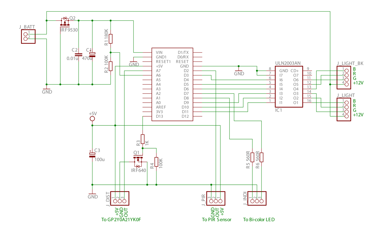
This is the initial phase of an Arduino-controlled PWM RGB LED project, which incorporates distance and PIR sensor control along with a sleep mode feature.
The project utilizes an Arduino microcontroller to manage a Pulse Width Modulation (PWM) RGB LED, allowing...

Appliance Remote Control Arduino Project
Starting today, interesting Arduino projects from various sources will be shared. The author is a novice in this field but is committed to understanding it fully. It should be noted that the projects are not developed by the author, and...

Temperature Displayed on 4 Digit 7 segment using Arduino
The intention is to utilize this code in future projects involving 7-segment displays. For those interested in learning more about 7-segment displays, additional information can be found in a related post.
7-segment displays are widely used in electronic devices for visual...

Handy Cricket Hardware Description
This document presents an overview of the hardware design of the Handy Cricket.
The Handy Cricket is a compact electronic device designed for educational and recreational purposes, primarily aimed at children. The hardware design incorporates various components that work together to...
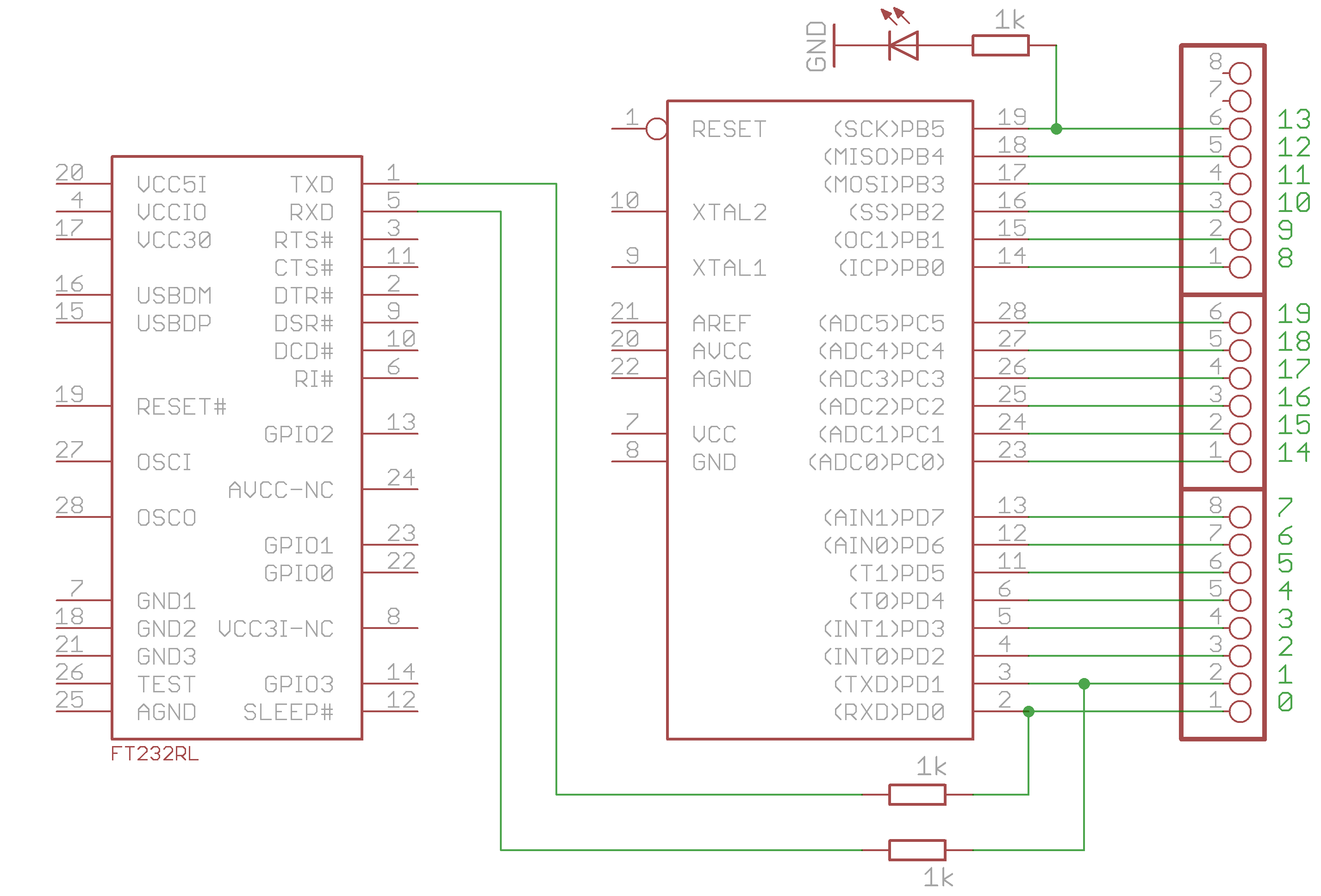
Blinken light
The example programs and Arduino sketches provided are free software.
The provided example programs and Arduino sketches serve as a valuable resource for developers and hobbyists working with Arduino microcontrollers. These software tools are designed to facilitate learning and experimentation with...

Arduino UNO
The Arduino Uno schematic diagram is available for viewing. The Arduino Uno is a microcontroller board that utilizes the ATmega328 chip. It features 14 digital input/output pins, of which 6 can be used as PWM outputs, and 6 analog input...