


Mendel heated bed
#heated bed
#3D printing
#RepRap
#temperature control
#ABS plastic
#fused-filament-fabrication
#warp prevention
#DIY electronics

Description: When constructing fused-filament-fabrication parts, such as those utilized by RepRap, it is important to note that these parts tend to warp as they cool from the bottom up when produced at room temperature. This warping occurs because the upper layers shrink during cooling, causing the already solidified lower layers to bend upwards. Different types of plastics exhibit varying degrees of this issue, with ABS being particularly prone to warping compared to other materials. In contrast, Polylactic Acid (PLA) performs better in this regard. When printing a single PLA part, curling is generally not a concern, as the part remains warm enough between layers to mitigate this issue almost entirely. However, when printing multiple parts simultaneously, even with PLA, some curling may occur. The solution to this problem is to utilize a heated bed, which is especially beneficial for printing PLA parts, though it may not reach adequate temperatures for ABS without further experimentation. Additional information about alternatives for the heated bed materials, electronic circuits, firmware, and Skeinforge configuration can be found on the Heated Bed page. The heated bed's primary component is made from Dibond, a composite material consisting of LDPE sandwiched between two aluminum sheets, providing a lightweight, rigid, and flat surface ideal for RepRap builds. The heated bed consists of a Dibond sheet with heating wires and insulation attached to the underside. The Dibond can be sourced from suppliers who can cut it into specific dimensions, such as 232x260 mm. The cutting pattern for a 3 mm thick Dibond is available in a CAD download, matching the standard Mendel build bed with an added tab at the rear for electrical connections. The dimensions of this tab may need to be adjusted based on the electrical connectors used, with a recommended depth of 30 mm. Two of the three holes in the tab accommodate a three-way chocolate-block screw electrical connector capable of handling substantial current, while the third hole is designated for a small right-angled bracket for a thermistor connector to monitor the bed's temperature. It is crucial to ensure that the electrical connections, located on the underside of the bed during use, do not interfere with the printed parts or the M4 screws securing the right-hand Y-axis bar. Although laser cutting the Dibond may present challenges due to the aluminum, a bandsaw is recommended for shaping, followed by edge cleaning with a file to remove any imperfections. The initial electrical consideration pertains to the power required to maintain the bed at the desired temperature. Operating the bed at 55°C necessitates approximately 100 W of power with a duty cycle of around 70%. The design incorporates two resistors connected in parallel, each requiring a resistance of 3 ohms, constructed from additional parallel wires. The specific arrangement will depend on the resistivity of the chosen heating wire, which is typically nichrome and does not require insulation. To achieve the desired total resistance, the resistance of a measured length of nichrome (e.g., 400 mm) can be calculated to establish an effective heating pattern across the bed. It is essential to ensure uniform current distribution to achieve even heating. A graph paper layout can be a practical method for planning this arrangement, which will include three copper wires and two ladders of nichrome.
The design of the heated bed is crucial for effective 3D printing, particularly when using materials that are sensitive to temperature changes, such as ABS and PLA. The heated bed not only helps to prevent warping but also ensures better adhesion of the first layer to the build surface, which is critical for the overall success of the print. The use of Dibond as a substrate material allows for a lightweight yet sturdy construction, making it suitable for the dynamic environment of a 3D printer.
The incorporation of a thermistor for temperature monitoring is vital for maintaining consistent heating. The thermistor provides feedback to the control system, allowing for precise temperature regulation. This feedback loop is essential for optimizing print quality and preventing overheating, which can lead to material degradation or fire hazards.
When selecting nichrome wire for the heating element, it is important to consider the gauge of the wire, as it affects the current-carrying capacity and resistance. The layout of the heating elements should be designed to minimize cold spots and ensure uniform heat distribution across the bed surface.
In conclusion, the careful design and assembly of the heated bed, along with appropriate materials and components, play a significant role in the success of 3D printing applications. Ensuring adequate power supply and effective thermal management will lead to improved print quality and reliability in the production of fused-filament-fabrication parts.If you build fused-filament-fabrication parts (the technology that RepRap uses) at room temperature, they have a tendency to curl as they cool from the bottom up. This is caused by higher layers shrinking as they cool and bending the already-set lower layers upwards.
Different plastics suffer from this problem to different extents. ABS warps morethan most other materials. Polylactic acid (PLA) is quite good. Indeed, if you make a single PLA part in your RepRap, curling probably won`t be a problem at all - the part will stay warm enough from one layer to the next to eliminate the problem almost completely. But if you build whole trays of parts (as in the picture) then, even using PLA, you can get some curling.
The cure for this is to build on a bed that is heated. This heated bed is primarily for making polylactic acid (PLA) parts. It probably won`t run hot enough for ABS. But that guess is subject to correction by experiment. See also Heated_Bed page which have other alternatives materials (may be easier to source locally, more cheap, etc) for making the Mendel Heated Bed. That page have also more information about the Heated Bed, electronic circuits, firmware, Skeinforge configuration for Heated Bed, etc.
The main part of the heated bed is made from Dibond. This is a sandwich of LDPE between two sheets of aluminium. It is very light, very stiff and very flat - all required properties for a RepRap build bed. The bed is made from a sheet of Dibond with heating wires and insulation attached underneath. I bought my Dibond from these people who kindly cut it into rectangles of 232x260 mm for me. It is pretty widely available as it is used for making signs and exhibition stands and such like. It`s also pretty cheap. This shows the pattern to be cut from 3 mm thick Dibond (the. dxf file for this is in the CAD download). The shape is exactly the same as the standard Mendel build bed, but with the addition of the tab at the back for mounting electrical connections. The dimensions of the tab are not shown because you may have to change them a bit to accommodate the electrical connectors you use.
My tab was 30 mm deep. Two of the three holes in the tab are for mounting a three-way chocolate-block screw electrical connector - get a chunky one; it has to handle a significant current. The third is for a small right-angled bracket to mount a connector for a thermistor that will be used to measure the bed`s temperature.
Virtually any small two-way connector will do for that. Make sure that the connections (which will be on the underside when the bed is in use) do not foul the two reprapped parts and the M4 screws through them that hold the right-hand Y-axis bar at the back of your Mendel. You could try cutting the Dibond in a laser cutter, but the aluminium may well give trouble if you do.
I found that a bandsaw worked best. If you saw out the shape, gently clean the edges with a file afterwards to remove any lips and burrs. The first electrical question that arises is obviously: how much power is needed to keep the bed at the right temperature I run my bed at 55oC (though see below), and that seems to need a little under 100 W at a duty cycle of about 70%.
As you can see, I set it up so the bed was effectively two resistors wired in parallel, so each one needed to be 3 ohms. They in turn are made up of additional wires in parallel. The exact pattern you use will depend on the resistivity of the heating wire you use. The heater wire I used was nichrome. It doesn`t need to be insulated. Measure the resistance of a length (say 400 mm) of your nichrome, then work out a regular pattern of it covering the bed that will give the total resistance that you want.
Make sure that all current paths are equal, so you get equal heating. Here I have laid out the pattern on graph paper, which is quite a convenient way of setting it up. There are three copper wires, with two ladders of nichrome
The design of the heated bed is crucial for effective 3D printing, particularly when using materials that are sensitive to temperature changes, such as ABS and PLA. The heated bed not only helps to prevent warping but also ensures better adhesion of the first layer to the build surface, which is critical for the overall success of the print. The use of Dibond as a substrate material allows for a lightweight yet sturdy construction, making it suitable for the dynamic environment of a 3D printer.
The incorporation of a thermistor for temperature monitoring is vital for maintaining consistent heating. The thermistor provides feedback to the control system, allowing for precise temperature regulation. This feedback loop is essential for optimizing print quality and preventing overheating, which can lead to material degradation or fire hazards.
When selecting nichrome wire for the heating element, it is important to consider the gauge of the wire, as it affects the current-carrying capacity and resistance. The layout of the heating elements should be designed to minimize cold spots and ensure uniform heat distribution across the bed surface.
In conclusion, the careful design and assembly of the heated bed, along with appropriate materials and components, play a significant role in the success of 3D printing applications. Ensuring adequate power supply and effective thermal management will lead to improved print quality and reliability in the production of fused-filament-fabrication parts.If you build fused-filament-fabrication parts (the technology that RepRap uses) at room temperature, they have a tendency to curl as they cool from the bottom up. This is caused by higher layers shrinking as they cool and bending the already-set lower layers upwards.
Different plastics suffer from this problem to different extents. ABS warps morethan most other materials. Polylactic acid (PLA) is quite good. Indeed, if you make a single PLA part in your RepRap, curling probably won`t be a problem at all - the part will stay warm enough from one layer to the next to eliminate the problem almost completely. But if you build whole trays of parts (as in the picture) then, even using PLA, you can get some curling.
The cure for this is to build on a bed that is heated. This heated bed is primarily for making polylactic acid (PLA) parts. It probably won`t run hot enough for ABS. But that guess is subject to correction by experiment. See also Heated_Bed page which have other alternatives materials (may be easier to source locally, more cheap, etc) for making the Mendel Heated Bed. That page have also more information about the Heated Bed, electronic circuits, firmware, Skeinforge configuration for Heated Bed, etc.
The main part of the heated bed is made from Dibond. This is a sandwich of LDPE between two sheets of aluminium. It is very light, very stiff and very flat - all required properties for a RepRap build bed. The bed is made from a sheet of Dibond with heating wires and insulation attached underneath. I bought my Dibond from these people who kindly cut it into rectangles of 232x260 mm for me. It is pretty widely available as it is used for making signs and exhibition stands and such like. It`s also pretty cheap. This shows the pattern to be cut from 3 mm thick Dibond (the. dxf file for this is in the CAD download). The shape is exactly the same as the standard Mendel build bed, but with the addition of the tab at the back for mounting electrical connections. The dimensions of the tab are not shown because you may have to change them a bit to accommodate the electrical connectors you use.
My tab was 30 mm deep. Two of the three holes in the tab are for mounting a three-way chocolate-block screw electrical connector - get a chunky one; it has to handle a significant current. The third is for a small right-angled bracket to mount a connector for a thermistor that will be used to measure the bed`s temperature.
Virtually any small two-way connector will do for that. Make sure that the connections (which will be on the underside when the bed is in use) do not foul the two reprapped parts and the M4 screws through them that hold the right-hand Y-axis bar at the back of your Mendel. You could try cutting the Dibond in a laser cutter, but the aluminium may well give trouble if you do.
I found that a bandsaw worked best. If you saw out the shape, gently clean the edges with a file afterwards to remove any lips and burrs. The first electrical question that arises is obviously: how much power is needed to keep the bed at the right temperature I run my bed at 55oC (though see below), and that seems to need a little under 100 W at a duty cycle of about 70%.
As you can see, I set it up so the bed was effectively two resistors wired in parallel, so each one needed to be 3 ohms. They in turn are made up of additional wires in parallel. The exact pattern you use will depend on the resistivity of the heating wire you use. The heater wire I used was nichrome. It doesn`t need to be insulated. Measure the resistance of a length (say 400 mm) of your nichrome, then work out a regular pattern of it covering the bed that will give the total resistance that you want.
Make sure that all current paths are equal, so you get equal heating. Here I have laid out the pattern on graph paper, which is quite a convenient way of setting it up. There are three copper wires, with two ladders of nichrome

Temperature controller
Temperature control is accomplished using the REF-02 +5 V Reference/Thermometer in conjunction with the CMP-02 Precision Low Input Current Comparator. The CMP-02 activates a heating element driver (Q1) whenever the current temperature falls below a predetermined setpoint, which is established...

Boiler control circuit
A boiler control circuit is designed to regulate the temperature of water in a hot water heating system. This circuit typically utilizes a comparator's comparison function to manage the heating equipment. The circuit includes a thermistor that forms a voltage...

Temperature Controller
Wine doesn't like subzero temperatures, and during wintertime, my wine cellar got pretty cold. There was an electric heating element, but the thermostat was broken, so it was either full burn or nothing. That's how the temperature monitor/controller came to...

Temperature controlled fan regulator
This fan regulator circuit automatically controls the speed of a fan based on temperature. It utilizes two thermistors (R1 and R2) for temperature sensing. The operation is similar to previously published designs, with thermistors replacing the potentiometer. As the temperature...
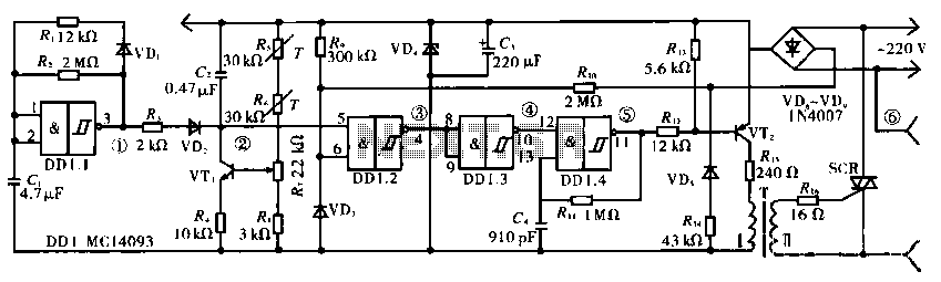
Household savings vegetable compartment temperature stabilizer circuit
The circuit operates using a temperature stabilizer derived from the main oscillator (DD1.1), along with components including C1, R1, R2, and VD1. It incorporates a monostable multivibrator formed by R3, VD2, VT1, C2, R4, DD1.2, R7, and R8, as well...

Temperature-controlling circuit
The circuit switches the current to an electrical heater on and off to maintain the temperature of a room at 25 ±0.5°C. The temperature sensor is a thermistor that provides a differential input (for reduced noise) to an operational amplifier....

Temperature-Controlled Soldering Iron
One reason why commercial soldering stations are expensive is that they typically require soldering irons with built-in temperature sensors.
Commercial soldering stations are designed to provide precise temperature control and consistency during soldering operations, which is essential for achieving reliable and...
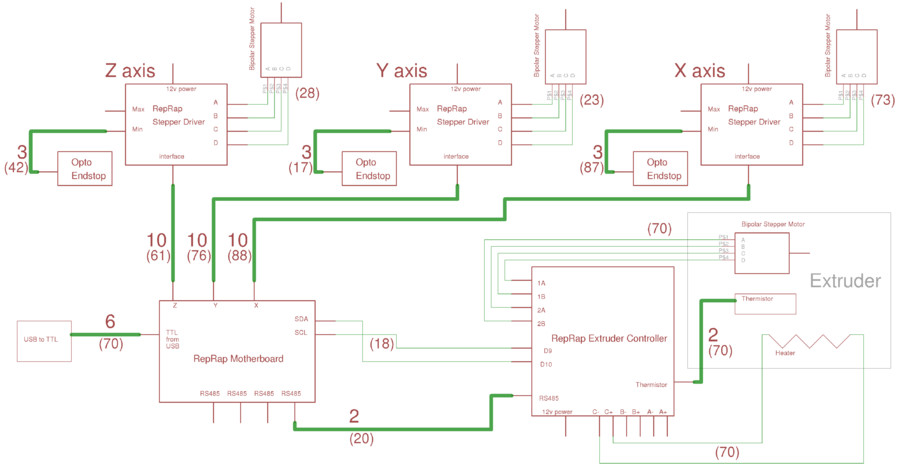
Mendel Electronic Wiring
This page outlines the wiring procedure for the RepRap Version II "Mendel." Prior to connecting the machine, it is essential to test the circuit boards individually, as detailed on this page. The overall Mendel wiring diagram is available; clicking the...

Temperature Controler switch
This circuit controls a load (in this case a DC brushless fan) based on a temperature compared with a setpoint. The transducer is a diode in the forward polarization regime. In fact, when forward biased, the forward voltage drop across...