


Pipe Descaler
#water descaler
#electromagnetic
#DIY
#home improvement
#pipe maintenance
#consumer electronics
#energy efficiency
#water treatment
#household
#appliances
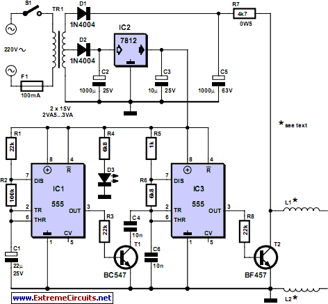
Description: Magnetic or electromagnetic water descaler devices have become increasingly available in Home Improvement and DIY stores across Europe. Despite numerous studies conducted by manufacturers and consumer associations, a definitive conclusion regarding the efficiency of commercial pipe descalers remains elusive. Given the relatively high cost of such electronic devices, this project has been proposed to allow individuals to evaluate the condition of their own faucets, pots, and other plumbing systems at a fraction of the price. The project features a device comparable to high-end models available on the market, incorporating a bi-frequency option that is believed to be effective against lime scale deposits. The initial astable oscillator, utilizing a standard 555 timer (IC3), operates at approximately 10 kHz when the only capacitor (C6) is in use, meaning that transistor T1 is blocked. T1 is activated by another astable oscillator based on IC1, which operates at around 1 Hz. When T1 is engaged by IC1, capacitor C4 is effectively connected in parallel with C6, reducing the frequency produced by IC3 to approximately 5 kHz. To ensure high amplitude signals, the power supply employs a mid-point transformer in a non-standard configuration with simple half-wave rectification. The first half of the secondary winding provides 15 VAC, which is then rectified, filtered, and regulated by IC2 to deliver a stable 12 VDC to power the oscillators. The entire secondary winding allows for approximately 40 VDC after rectification, which powers coils L1 and L2, wrapped around the pipes to be treated. Following IC3, a high-voltage transistor (T2, such as a BF457 or equivalent) modulates this high voltage at frequencies of 5 or 10 kHz, depending on the state of IC1. An LED (D3) indicates the presence of power supply. Coils L1 and L2 are simple inductors made from insulated flexible wire, each containing about ten turns, and are to be wound around the water-carrying pipes, spaced approximately ten centimeters apart. The material and diameter of the piping system should not affect the device's efficiency. Interestingly, one end of these coils is left exposed, which may seem unconventional; however, the primary aim of this project is not to explain the underlying principles but to enable users to construct a device similar to those available commercially for personal experimentation.
The schematic for this magnetic water descaler encompasses several key components and configurations. The primary control unit consists of two astable oscillators: IC1, which operates at a low frequency of 1 Hz, and IC3, which operates at a higher frequency of approximately 10 kHz. The output of IC3 is modulated by T1, which acts as a switch controlled by IC1, allowing for the frequency division to approximately 5 kHz when activated.
The power supply circuit begins with a mid-point transformer that provides the necessary voltage levels. The secondary winding is configured to output 15 VAC, which is subsequently rectified using a half-wave rectifier circuit. The rectified voltage is filtered and regulated to produce a stable 12 VDC output for powering the oscillators, while the full secondary winding allows for a higher voltage output of around 40 VDC, which is necessary for driving the coils.
Transistor T2 is crucial in this setup, as it chops the high voltage output from IC3 into the desired frequency range, effectively driving the coils L1 and L2. These coils, designed to be wound around the pipes, serve as inductive elements that interact with the water flow. The spacing of approximately ten centimeters between the coils is intended to optimize the electromagnetic field's effectiveness.
The overall design emphasizes simplicity and efficacy, allowing users to construct a functional water descaler that mirrors commercial products without delving deeply into the theoretical aspects of electromagnetic water treatment. The inclusion of an LED indicator (D3) provides a straightforward means of verifying that the device is powered and operational, enhancing usability and user experience.Magnetic (or electromagnetic) water descaler devices have been showing up on the shelves of Home Improvement and other DIY stores all over Europe. Despite the numerous studies completed on that subject, by manufacturers as well as by various consumer associations, none have been able to conclude on the efficiency of commercial
pipe descalers in a decisive manner. Since electronic devices of this type are relatively expensive (especially when we discover what they are made of!), we decided to offer this project to our readers. For the price of a few tens of pounds, you will be able to evaluate the state of your own faucets, pots, and other pipes.
The device we`re offering as a project is identical to top-of-the-line items found on sale; in other words, it includes the bi-frequency option because it seemed that would be the best way to fight lime scale deposits. An initial astable oscillator, based on a traditional 555, labeled IC3, functions at around 10 kHz when the only capacitor C6 is operating; in other words, when T1 is blocked.
The latter is controlled by another astable oscillator, based on IC1 this time, but which functions at about 1 Hz. When T1 is turned on by IC1, capacitor C4 is effectively in parallel with C6 which divides the frequency produced by IC3 by two, i.
e. to about 5 kHz. In order to have high amplitude signals, the power supply operates with a mid-point transformer utilized in an unconventional way, with simple half-wave rectification. The first half of the secondary delivers 15 VAC which, after being rectified, filtered and regulated by IC2, supply stable current of 12 VDC to supply power to the oscillators.
The entire secondary makes it possible to have available, after rectification, approximately 40 VDC which is used to supply power to coils L1 and L2, wound around the pipe systems on which the assembly will work. To do that, IC3 is followed by high-voltage transistor T2 (a BF457 or equivalent) which chops this high voltage to 5 or 10 kHz frequency depending on the state of IC1.
LED D3 lights up to signal that the power supply is present. Coils L1 and L2 are simple inductors made from insulated flexible wire, with about ten windings each. They have to be wound around the pipes carrying the water to be treated` and are spaced about ten centimeters from each other.
Neither the material of the pipe system, nor its diameter, should have any influence on the efficiency of the device. Paradoxically, these coils have one end in the air, which may surprise you as much as us but we indicated at the beginning of this article, that our goal with this project is not to explain the principle but rather to allow you to make the same device as those sold in stores, so that you can perform your own tests.
The schematic for this magnetic water descaler encompasses several key components and configurations. The primary control unit consists of two astable oscillators: IC1, which operates at a low frequency of 1 Hz, and IC3, which operates at a higher frequency of approximately 10 kHz. The output of IC3 is modulated by T1, which acts as a switch controlled by IC1, allowing for the frequency division to approximately 5 kHz when activated.
The power supply circuit begins with a mid-point transformer that provides the necessary voltage levels. The secondary winding is configured to output 15 VAC, which is subsequently rectified using a half-wave rectifier circuit. The rectified voltage is filtered and regulated to produce a stable 12 VDC output for powering the oscillators, while the full secondary winding allows for a higher voltage output of around 40 VDC, which is necessary for driving the coils.
Transistor T2 is crucial in this setup, as it chops the high voltage output from IC3 into the desired frequency range, effectively driving the coils L1 and L2. These coils, designed to be wound around the pipes, serve as inductive elements that interact with the water flow. The spacing of approximately ten centimeters between the coils is intended to optimize the electromagnetic field's effectiveness.
The overall design emphasizes simplicity and efficacy, allowing users to construct a functional water descaler that mirrors commercial products without delving deeply into the theoretical aspects of electromagnetic water treatment. The inclusion of an LED indicator (D3) provides a straightforward means of verifying that the device is powered and operational, enhancing usability and user experience.Magnetic (or electromagnetic) water descaler devices have been showing up on the shelves of Home Improvement and other DIY stores all over Europe. Despite the numerous studies completed on that subject, by manufacturers as well as by various consumer associations, none have been able to conclude on the efficiency of commercial
pipe descalers in a decisive manner. Since electronic devices of this type are relatively expensive (especially when we discover what they are made of!), we decided to offer this project to our readers. For the price of a few tens of pounds, you will be able to evaluate the state of your own faucets, pots, and other pipes.
The device we`re offering as a project is identical to top-of-the-line items found on sale; in other words, it includes the bi-frequency option because it seemed that would be the best way to fight lime scale deposits. An initial astable oscillator, based on a traditional 555, labeled IC3, functions at around 10 kHz when the only capacitor C6 is operating; in other words, when T1 is blocked.
The latter is controlled by another astable oscillator, based on IC1 this time, but which functions at about 1 Hz. When T1 is turned on by IC1, capacitor C4 is effectively in parallel with C6 which divides the frequency produced by IC3 by two, i.
e. to about 5 kHz. In order to have high amplitude signals, the power supply operates with a mid-point transformer utilized in an unconventional way, with simple half-wave rectification. The first half of the secondary delivers 15 VAC which, after being rectified, filtered and regulated by IC2, supply stable current of 12 VDC to supply power to the oscillators.
The entire secondary makes it possible to have available, after rectification, approximately 40 VDC which is used to supply power to coils L1 and L2, wound around the pipe systems on which the assembly will work. To do that, IC3 is followed by high-voltage transistor T2 (a BF457 or equivalent) which chops this high voltage to 5 or 10 kHz frequency depending on the state of IC1.
LED D3 lights up to signal that the power supply is present. Coils L1 and L2 are simple inductors made from insulated flexible wire, with about ten windings each. They have to be wound around the pipes carrying the water to be treated` and are spaced about ten centimeters from each other.
Neither the material of the pipe system, nor its diameter, should have any influence on the efficiency of the device. Paradoxically, these coils have one end in the air, which may surprise you as much as us but we indicated at the beginning of this article, that our goal with this project is not to explain the principle but rather to allow you to make the same device as those sold in stores, so that you can perform your own tests.

Some Thoughts on Nazi Disc Shaped Flying Machines
There are two methods to counteract the effects of gravity using electromagnetic forces:
1. The first method involves a rotating magnetic field combined with a radial current flow. The resulting force is directed according to the vector cross product of...

Making Electromagnetic Weapons
This series focuses on creating Electromagnetic Weapons, specifically highlighting the Electromagnetic Pulse Generator. The last three articles provide further insights. Microwaves, commonly encountered in everyday life, utilize invisible energy to heat food, and can even produce sparks when metal is...

turret diy
For maximum mini-security, this RC Tupperware Turret delivers a formidable deterrent against food theft. While it lacks motion sensors, potential food thieves will think twice before attempting to swipe baked goods. This 11-hour project, designed by Chris of PyroElectro, emphasizes...
Help with a schematic please
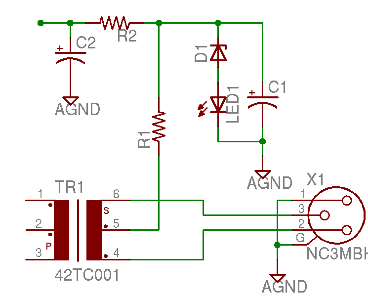
A project is underway to construct the CountryHick DI as illustrated on DIYFactory, incorporating a few minor modifications. The final design aims to be a 1U unit with four inputs.
The CountryHick DI (Direct Injection) box is a crucial tool in...
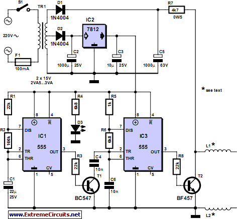
pipe descaler schematics
For many years, magnetic (or electromagnetic) water descaler devices have appeared on the shelves of home improvement and DIY stores across Europe. Despite numerous studies conducted by manufacturers and various consumer associations, none have definitively concluded on the effectiveness of...

Electromagnetic Ring Launcher Circuit
The electromagnetic ring launcher consists of four subcircuits: a clock circuit utilizing U5, a 555 oscillator/timer configured for astable operation; a countdown/display circuit incorporating U3, a 74190 synchronous up/down counter with BCD outputs set for countdown operation; U4, an ECG8368...
DIY kinetic energy harvester
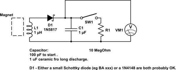
A DIY kinetic energy harvester utilizing the electromagnetic method to generate electricity. The materials that will be used are currently known.
The project involves creating a kinetic energy harvester that converts mechanical energy from motion into electrical energy through electromagnetic induction....
Glue stck torch
This project, developed around 2005, involves constructing a torch using a glue stick, which conveniently accommodates an AA battery within its plastic casing. To create a functional battery holder, contacts for both the positive and negative connections are necessary. The...

MePADS
If you are considering building the Desert Ratt 2, it is advisable to read all the accompanying text, as it contains relevant construction details. Engaging with the comments and replies can also provide additional insights, as previous blog posts have...