


Replacing heater block on fog machine
#fog machine
#heater block
#power supply
#repair
#wiring
#smoke machine
#electronics repair
#heater replacement

Description: The heater block of the smoke machine is broken and has been replaced with a new one. However, the old heater block was removed a long time ago, and the connections for the cables are unclear. A picture of the smoke machine has been attached for assistance. The new heater block differs from the old one in that it does not have crimp terminals for the power supply.
The smoke machine operates by generating vapor using a heater block, which is an essential component for the device's functionality. In this case, the replacement heater block requires careful attention to the wiring connections to ensure proper operation. Typically, heater blocks have specific terminals for power supply connections, which may include positive and negative terminals, as well as additional connections for temperature sensors or safety cut-offs.
To facilitate the installation of the new heater block, it is important to reference the manufacturer's specifications for the smoke machine model in question. This documentation may provide a wiring diagram or pinout that outlines the correct connections for the power supply and any additional components. If the new heater block lacks crimp terminals, alternative connection methods such as soldering or using screw terminals may be necessary.
When connecting the wires, ensure that the power supply is disconnected to prevent any electrical hazards. Identify the positive and negative leads from the power supply and match them to the corresponding terminals on the new heater block. It may also be beneficial to check for any additional connectors that may be present, such as those for a thermal switch or a fan, if applicable.
Once all connections are made, double-check for secure connections and proper insulation to avoid short circuits. After confirming that everything is correctly wired, power the smoke machine on and monitor its operation to ensure that the new heater block is functioning as intended. If issues arise, further troubleshooting may be required, which could involve checking for continuity in the wiring or testing the heater block's resistance.My smoke machine heater block has broken so I bought a new one, however I removed the old heater block ages ago and I cant remember what cables go where, I have attached a picture of my smoke machine in hope that someone can help me. The only difference between this heater block and the old one is that this heater doesn`t have crimp terminals for the power supply where as the old one did.
Thanks.
The smoke machine operates by generating vapor using a heater block, which is an essential component for the device's functionality. In this case, the replacement heater block requires careful attention to the wiring connections to ensure proper operation. Typically, heater blocks have specific terminals for power supply connections, which may include positive and negative terminals, as well as additional connections for temperature sensors or safety cut-offs.
To facilitate the installation of the new heater block, it is important to reference the manufacturer's specifications for the smoke machine model in question. This documentation may provide a wiring diagram or pinout that outlines the correct connections for the power supply and any additional components. If the new heater block lacks crimp terminals, alternative connection methods such as soldering or using screw terminals may be necessary.
When connecting the wires, ensure that the power supply is disconnected to prevent any electrical hazards. Identify the positive and negative leads from the power supply and match them to the corresponding terminals on the new heater block. It may also be beneficial to check for any additional connectors that may be present, such as those for a thermal switch or a fan, if applicable.
Once all connections are made, double-check for secure connections and proper insulation to avoid short circuits. After confirming that everything is correctly wired, power the smoke machine on and monitor its operation to ensure that the new heater block is functioning as intended. If issues arise, further troubleshooting may be required, which could involve checking for continuity in the wiring or testing the heater block's resistance.My smoke machine heater block has broken so I bought a new one, however I removed the old heater block ages ago and I cant remember what cables go where, I have attached a picture of my smoke machine in hope that someone can help me. The only difference between this heater block and the old one is that this heater doesn`t have crimp terminals for the power supply where as the old one did.
Thanks.
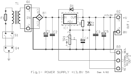
Circuit diagrams and Schematic
This AC to DC power supply can output 5A in continuous operation and 12A peak current. This type of DC power supply uses a PCB, allowing for two case types for IC1: TO-220 or TO-3. The regulation of this 12-volt...

Dragon -ZL-2801A DVD machine type switching power supply circuit
The Dragon ZL-2801A is a DVD machine that utilizes a switching power supply circuit. The circuit primarily consists of an AC input circuit, a rectifier filter wave circuit, an oscillation circuit switch, a switch transformer (Tl), a secondary rectifier, and...

Power Supply Monitor /Memory Protector
This circuit detects low-voltage supply conditions, down to 0.6 V. Diode D1 sets the trip point of the circuit. The circuit is useful for protecting memory circuits from accidental writes during low-voltage power supply conditions, which can cause other circuits...

A typical DVD switching power supply circuit
A typical DVD switching power supply circuit is shown in the standby power supply circuit of digital products. It utilizes a switching power supply structure, with the oscillation switch IC EA1623 providing oscillation pulses to the transformer. The secondary output...

Batteries charger & PSU - ideal for digital camerass
This circuit was designed for digital cameras, which are known to have significant power consumption. For instance, the Minolta E223 camera requires approximately 800 mA. In practice, this demand can be met using a mains power supply or high-capacity NiMH...

Battery charger or Power Supply 14 volt 4 ampere
The schematic diagram originates from a circuit designed as a battery charger/power supply with an output of 14V and a maximum current of 4A, utilizing the VN64GA MOSFET. This high-performance battery charger is specifically engineered for gelled electrolyte lead-acid batteries,...

PM4040F application circuit switching power supply drive
The PM4040F is utilized in switching power supply applications for medium power ranges. It is designed to drive power supplies between 200W and 800W, as illustrated in the accompanying bridge circuit. For power applications below 1000W, an alternative circuit configuration...

power supply alarm circuit
Most of the power supply failure indicator circuits need a separate power supply for themselves. But the alarm circuit presented here needs no additional supply source. It employs an electrolytic capacitor to store adequate charge, to feed power to the...

Output sampling winding isolated switching power supply
The diagram illustrates the output sampling winding of an isolated switching power supply. In the diagram, T represents a high-frequency transformer; N2 denotes the self-oscillation positive feedback winding; N3 is the error amplifier; VTS is the winding that provides the...