


Scoring Game Circuit-DescriptionCircuit PartsDiagram
#game circuit
#scoring system
#circuit diagram
#electronic game
#educational
#fun project
#DIY
#hobby electronics
#interactive
#score display

Description: A scoring game circuit is explained with a circuit diagram and circuit parts.
The scoring game circuit is designed to track and display scores in a gaming environment. The primary components of this circuit typically include a microcontroller, a score display (such as a seven-segment display), input buttons for score adjustments, and a power supply.
The microcontroller serves as the central processing unit, where the game logic is implemented. It receives input from the buttons, which are used to increase or decrease the score. The circuit diagram will illustrate the connections between the microcontroller, the display, and the buttons.
The score display is connected to the microcontroller through a series of output pins, which send signals to determine which segments of the display should be illuminated. Commonly, a seven-segment display is used to visually represent the score, with each segment corresponding to a specific numeral.
Power supply considerations are essential for the circuit, ensuring that all components operate within their specified voltage and current ratings. A regulated power supply may be employed to provide a stable voltage to the microcontroller and display.
Additional features may include sound effects for score adjustments, which can be achieved by integrating a small speaker or buzzer connected to the microcontroller. This adds an auditory feedback element, enhancing the user experience during gameplay.
Overall, the scoring game circuit combines various electronic components to create an interactive and engaging scoring system suitable for games of different types. The schematic representation of the circuit will detail the interconnections and functional relationships between all components, ensuring clarity in the design and implementation process.A scoring game circuit is explained with circuit diagram, and circuit parts..
The scoring game circuit is designed to track and display scores in a gaming environment. The primary components of this circuit typically include a microcontroller, a score display (such as a seven-segment display), input buttons for score adjustments, and a power supply.
The microcontroller serves as the central processing unit, where the game logic is implemented. It receives input from the buttons, which are used to increase or decrease the score. The circuit diagram will illustrate the connections between the microcontroller, the display, and the buttons.
The score display is connected to the microcontroller through a series of output pins, which send signals to determine which segments of the display should be illuminated. Commonly, a seven-segment display is used to visually represent the score, with each segment corresponding to a specific numeral.
Power supply considerations are essential for the circuit, ensuring that all components operate within their specified voltage and current ratings. A regulated power supply may be employed to provide a stable voltage to the microcontroller and display.
Additional features may include sound effects for score adjustments, which can be achieved by integrating a small speaker or buzzer connected to the microcontroller. This adds an auditory feedback element, enhancing the user experience during gameplay.
Overall, the scoring game circuit combines various electronic components to create an interactive and engaging scoring system suitable for games of different types. The schematic representation of the circuit will detail the interconnections and functional relationships between all components, ensuring clarity in the design and implementation process.A scoring game circuit is explained with circuit diagram, and circuit parts..
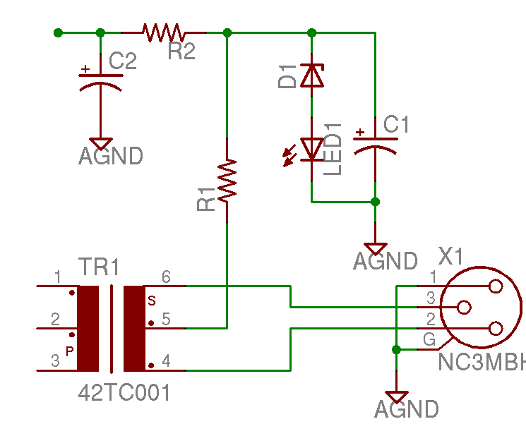
Help with a schematic please
A project is underway to construct the CountryHick DI as illustrated on DIYFactory, incorporating a few minor modifications. The final design aims to be a 1U unit with four inputs.
The CountryHick DI (Direct Injection) box is a crucial tool in...

Reflex Action Game
This circuit is designed for quiz events where two participants press their buttons to answer questions. The participant who presses their button first gets the opportunity to answer first, as indicated by the lamps associated with each button. When switch...
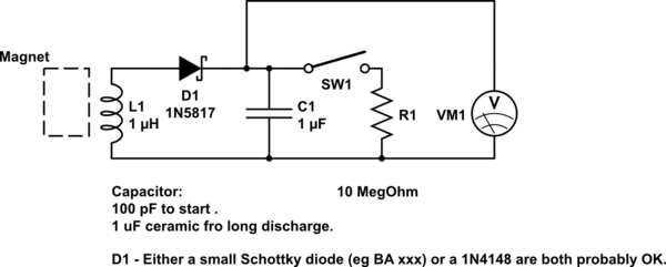
DIY kinetic energy harvester
A DIY kinetic energy harvester utilizing the electromagnetic method to generate electricity. The materials that will be used are currently known.
The project involves creating a kinetic energy harvester that converts mechanical energy from motion into electrical energy through electromagnetic induction....

Homemade Metal Detector Kit
A simple home project can quickly become problematic if it encounters electric cables, gas, or water pipes, or the central heating system. Using a metal detector allows one to check for metal objects within walls, ceilings, or floors beforehand. An...

how to convert a 9v battery to 3.7v
A regulator circuit is needed for this DIY project. Familiarity with electronic components, circuitry, the use of a multitester, and a soldering iron is essential. The schematic diagram provided can accept an input voltage ranging from 6 to 24 volts...

Fastest Finger First Indicator
Quiz-type game shows are increasingly popular on television. In these games, fastest finger first indicators (FFFIs) are used to test players' reaction times. When a player presses their entry button, their designated number is displayed alongside an audio alarm. The...

White Light
White Light is an interactive sound and light installation that combines elements of sculpture, musical instrument, and social engagement. It invites viewers to participate in a complex display of sound and light by manipulating controls on one of three podiums...

Scoring Game circuit
You can play this game alone or with your friends. The circuit comprises a timer IC, two decade counters and a display driver along with a 7-segment display. The game is simple. As stated above, it is a scoring game...

Pot shot
This circuit is designed for a shooting gallery-style game. IC2a and IC2b function as an astable multivibrator, generating a clock signal for IC1, which sequentially activates LEDs 1 through 8. LED 5 serves as the target LED, and the objective...