


2Y- connection two-speed motor contactor control circuit 2
#two-speed motor
#contactor control
#low speed
#2kW motor
#simple circuit
#motor driver
#electrical control
#industrial
#wiring
#power management

Description: The circuit illustrated in Figure 3-97 features two contacts and is designed specifically for a 2kW dual-speed motor. In this configuration, SB1 is utilized for low-speed operation, while SB2 serves as the high-speed run button.
The circuit operates by allowing the user to select between two distinct speed settings for the motor, enabling efficient performance based on the application's requirements. The low-speed setting, activated by the SB1 button, is typically used for tasks that require more torque and less speed, making it suitable for applications such as starting heavy loads or operating machinery that benefits from controlled acceleration. Conversely, the high-speed setting, engaged through the SB2 button, facilitates faster operation, ideal for tasks that require quick movement or reduced processing time.
The two contacts in the circuit serve as switches that control the flow of current to the motor, effectively changing its operational speed. The design ensures that only one speed can be active at a time, preventing potential damage to the motor or the circuit itself. This is often achieved through a simple relay or contactor mechanism that engages the appropriate speed setting based on the button pressed.
In summary, the circuit in Figure 3-97 represents a straightforward yet effective solution for controlling a dual-speed motor, optimizing its performance for varying operational demands. The clear distinction between low and high-speed operation, facilitated by the respective buttons, enhances usability and operational flexibility. Circuit shown in Figure 3-97. The circuit only two contacts, the circuit is simple, but only applies to the following 2kW dual speed motor. Figure, SBi is running at low speed button, SBz high-speed run button.
The circuit operates by allowing the user to select between two distinct speed settings for the motor, enabling efficient performance based on the application's requirements. The low-speed setting, activated by the SB1 button, is typically used for tasks that require more torque and less speed, making it suitable for applications such as starting heavy loads or operating machinery that benefits from controlled acceleration. Conversely, the high-speed setting, engaged through the SB2 button, facilitates faster operation, ideal for tasks that require quick movement or reduced processing time.
The two contacts in the circuit serve as switches that control the flow of current to the motor, effectively changing its operational speed. The design ensures that only one speed can be active at a time, preventing potential damage to the motor or the circuit itself. This is often achieved through a simple relay or contactor mechanism that engages the appropriate speed setting based on the button pressed.
In summary, the circuit in Figure 3-97 represents a straightforward yet effective solution for controlling a dual-speed motor, optimizing its performance for varying operational demands. The clear distinction between low and high-speed operation, facilitated by the respective buttons, enhances usability and operational flexibility. Circuit shown in Figure 3-97. The circuit only two contacts, the circuit is simple, but only applies to the following 2kW dual speed motor. Figure, SBi is running at low speed button, SBz high-speed run button.

Power Path Management Battery Charger
Powering the system is required by many applications while charging the battery simultaneously. Interaction between the system and charger may result in a...
Power management in electronic systems is critical, particularly in applications that necessitate simultaneous operation and battery charging. This...

Big Trak Motor Driver Schematic
Schematic of Big Trak's motor driver circuit. The toy includes 9112 and 9113 transistors (and sometimes 2N6715) because the 75494 chip cannot supply enough current to run the Big Trak's motors by itself.
The motor driver circuit for the Big Trak...

Custom Motor Driver
This chapter was removed from Applied Robotics 2 due to space constraints. It addresses general motor control issues and details the construction of a 5-amp motor driver. The principles discussed can be applied to larger motor controllers. Although commercially available...

Computer Off Switch
How often does it happen that a user shuts down Windows and then forgets to turn off the computer? This circuit automates that process. After Windows is shut down, a click occurs a second later, disconnecting the PC from the...

2Y- connection two-speed motor contactor control circuit of the four
The circuit depicted in Figure 3-99 illustrates a low start-up mechanism for a motor, which transitions to high-speed operation automatically. The start-up process is facilitated by a shaped connection, while the transition to high-speed operation is managed by a 2Y-connector....

smart amp delay
This system is designed as a Windows service that detects various power events, including Suspend, Hibernate, Reboot, and Shutdown. It can send appropriate responses to a control circuit, specifically a Heartbeat or Kill signal. The trigger mechanism is also regulated...
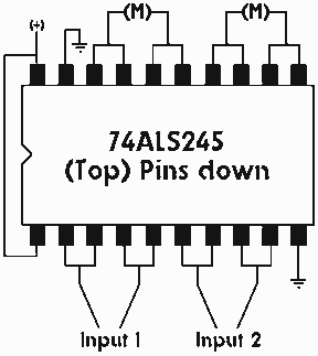
Single IC chip Motor Driver for robots
A motor driver is required in pretty much all walkers including all of my CW series walkers. You need to use it any time you need to supply more current to the motors because the circuit can't supply enough. This...

2 -Y-connected two-speed motor contactor control circuit
The circuit illustrated in Figure 3-104 features SB2, which functions as the low-speed operation button, and SBi, which serves as the high-speed operation button.
The circuit design utilizes two distinct operational buttons, SB2 and SBi, to control the speed of a...
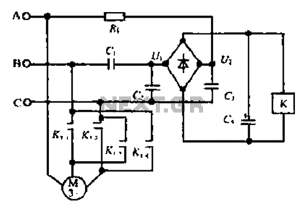
A motor reversing automatic adjustment circuit
Composition ratio circuit. The circuit consists of resistors and capacitors that form a shift register circuit with diodes VD1 to VD4, creating a bridge for electric current. Capacitor C4 is utilized for filtering applications and for eliminating instantaneous relay energization...