


A three-phase motor phase automatic protection circuit
#three-phase motor
#transformer
#induced voltage
#transistor
#phase protection
#rectifier
#motor safety
#current imbalance
#automatic protection

Description: Connect a transformer to the motor phase line when the induced voltage is zero volts. In cases of serious imbalance in one, two, or three phases, the transformer’s induced voltage increases rapidly, which leads to an immediate rectification of the transistor base current. When the transistor enters saturated conduction, the relay K activates, causing the normally closed contact to open. As a result, the contactor coil is de-energized, leading to a power loss and stopping the motor from running. The operating time for this process is less than one second.
This circuit employs a transformer to monitor the voltage levels across the motor phase lines. When the induced voltage drops to zero, indicating a potential fault condition or imbalance in the power supply, the transformer triggers a series of actions to protect the motor. The rapid rise in induced voltage during an imbalance condition is detected and processed, resulting in the rectification of the base current of a transistor.
The transistor is configured to operate in a switching mode. Once the base current reaches a certain threshold due to the rectification process, the transistor enters saturation, allowing current to flow through the relay coil. Relay K is used to control the power supply to the motor by operating its normally closed contact. Under normal conditions, this contact allows current to flow to the contactor coil, keeping the motor operational.
However, when the relay is activated due to the transistor's saturation, the normally closed contact opens, interrupting the power supply to the contactor coil. This action effectively de-energizes the coil, resulting in the disconnection of power to the motor. The circuit is designed to respond quickly, with an operating time of less than one second, ensuring that the motor is promptly stopped in the event of a serious phase imbalance, thereby preventing potential damage to the motor or associated equipment.
Overall, this circuit serves as a protective measure for motors operating in environments where phase imbalances may occur, ensuring reliable operation and safety.Penetrate the motor phase line with a transformer when the induced voltage is ov. When one phase or two-phase or three-phase serious imbalance, transformer induced voltage rises rapidly, resulting in the transistor base current after rectified immediately transistor saturated conduction, the relay K was electric suction units, normally closed contact off point, the contactor coil is oFF, touch -break, loss of power the motor stops running. Operating time is less than 1 second.
This circuit employs a transformer to monitor the voltage levels across the motor phase lines. When the induced voltage drops to zero, indicating a potential fault condition or imbalance in the power supply, the transformer triggers a series of actions to protect the motor. The rapid rise in induced voltage during an imbalance condition is detected and processed, resulting in the rectification of the base current of a transistor.
The transistor is configured to operate in a switching mode. Once the base current reaches a certain threshold due to the rectification process, the transistor enters saturation, allowing current to flow through the relay coil. Relay K is used to control the power supply to the motor by operating its normally closed contact. Under normal conditions, this contact allows current to flow to the contactor coil, keeping the motor operational.
However, when the relay is activated due to the transistor's saturation, the normally closed contact opens, interrupting the power supply to the contactor coil. This action effectively de-energizes the coil, resulting in the disconnection of power to the motor. The circuit is designed to respond quickly, with an operating time of less than one second, ensuring that the motor is promptly stopped in the event of a serious phase imbalance, thereby preventing potential damage to the motor or associated equipment.
Overall, this circuit serves as a protective measure for motors operating in environments where phase imbalances may occur, ensuring reliable operation and safety.Penetrate the motor phase line with a transformer when the induced voltage is ov. When one phase or two-phase or three-phase serious imbalance, transformer induced voltage rises rapidly, resulting in the transistor base current after rectified immediately transistor saturated conduction, the relay K was electric suction units, normally closed contact off point, the contactor coil is oFF, touch -break, loss of power the motor stops running. Operating time is less than 1 second.

50 Watt Amplifier Circuit Using Transistor
This circuit is a robust and efficient power amplifier suitable for various audio applications. It delivers 60W RMS output at a 50V supply with an 8 Ohm load. The design is user-friendly, allowing for the use of non-critical components that...
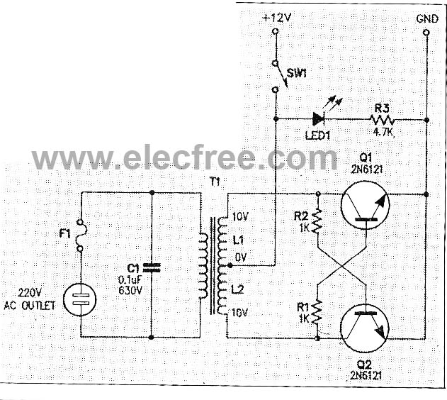
Micro Inverter by 2N6121
This micro inverter is a small-sized device that modifies energy from a battery, producing an output voltage of approximately 220V AC at 50Hz. The circuit comprises two transistors that function as a pulse oscillator or square wave generator, driving a...

Video amplifier splitter by transistor BD137-BC547-BC557
This is a video amplifier circuit or video splitter circuit, designed to strengthen video signals. It compensates for signal loss and is...
The video amplifier circuit serves as a crucial component in video signal distribution systems, ensuring that the integrity and...

Blinker circuit 2
The circuit depicted in Figure 13-4 utilizes triode control. Two transistors, VTi and VTz, are coupled via a capacitor (C) to alternately turn on and off, producing a flashing light effect. The flash frequency is influenced by the capacitance of...

audio tone control with 2 transistor
The first BC109C transistor functions as a buffer, offering the circuit an input impedance of approximately 250,000 ohms and a voltage gain just below unity. As the Baxandall tone control circuit is a passive design, it attenuates all audio frequencies....

Transistor act as a switch
A transistor is a semiconductor device utilized for switching and amplifying weak signals. This article details the operation of a transistor and its function as a switch. Currently, transistors are integrated into most electronic equipment for switching applications, with digital...

transistors LC circuit
Build the LC oscillator shown at the bottom of this page for a school project, but there are some challenges in translating the theoretical circuit into a real-world application. The understanding of the circuit's operation on paper is clear. It...

How to properly snub transient spikes from a transformer and prevent switch mode power supply burn out
The leads from the transformer to the circuit are quite long (>5m). The 110V side of the transformer has been switched off frequently, which likely caused a spike on the secondary (24V) side. The input pin of the LTC3631 shows...

transistors How does this circuit diagram work
R2 controls the charging speed of capacitor C1. At a specific charge level, C1 triggers transistors Q1 and Q2, which release a 9-volt pulse. This pulse generates a clicking sound. The discharge process of the capacitor involves it charging gradually...