


Automatic washing machine motor driver schematic

Description: The schematic for the automatic washing machine motor driver outlines the motor drive circuit for the Narcissus XQB30-III-type washing machine. The control circuit comprises four Triacs, four drive transistors, and a control chip. This setup allows for the activation of the corresponding thyristor when a high signal is received at the base of the transistor, thus controlling the electromagnetic components. During the washing cycle, a microcomputer program controller, linked to a foot switch, manages the water level and the solenoid valve, which governs water intake into the washing tub. When the water level reaches a pre-set threshold, the microcontroller commands the control transistor (VT6) to cease water injection. The microcontroller also regulates the conduction of transistors VT3 or VT4 to determine the motor's direction for washing clothes. Upon completion of the wash cycle, the microcontroller will deactivate transistors VT3 or VT4, stopping the motor, while transistor VT5 is activated to operate the drain solenoid valve. After one minute, the microcontroller will turn on transistors VT7 and V12, prompting the buzzer to sound.
The automatic washing machine motor driver schematic serves as a comprehensive representation of the control mechanisms involved in the operation of the Narcissus XQB30-III-type washing machine. The circuit's design integrates various components to ensure efficient motor control and water management during the washing process.
The four Triacs in the circuit are responsible for switching the motor's power supply, allowing for precise control of the motor's operation in both forward and reverse directions. This is critical for the washing and rinsing cycles, as the motor must operate in both directions to effectively agitate the laundry. The drive transistors amplify the control signals from the microcontroller, ensuring that the Triacs are triggered appropriately based on the washing program selected.
The microcontroller plays a central role in the operation of the washing machine. It processes inputs from the water level sensor and foot switch to regulate the solenoid valve's operation, ensuring that water is only added to the tub when necessary. The control logic embedded in the microcontroller dictates when to stop water intake, activate the motor, and manage the drain cycle effectively.
Transistors VT3 and VT4 are pivotal for determining the motor's direction. Depending on the washing program, the microcontroller activates one of these transistors to either forward or reverse the motor's rotation. This functionality is essential for the washing process, as it allows for thorough cleaning of the clothes through agitation.
At the end of the wash cycle, the microcontroller signals the motor to stop by turning off VT3 or VT4. It then activates VT5 to engage the drain solenoid valve, allowing water to exit the tub. The timing of these operations is carefully managed to ensure that the washing machine operates efficiently and effectively.
Finally, the inclusion of a buzzer, activated by transistors VT7 and V12, serves as an alert to the user that the washing cycle has completed. This feature enhances user experience by providing audible feedback on the machine's status. Overall, the schematic illustrates a well-coordinated system that integrates various electronic components to deliver a reliable and effective washing machine operation. Automatic washing machine motor driver schematic It shows the automatic washing machine motor drive circuit schematic. The circle of Narcissus XQB30-III-type washing machine mo tor drive circuit practical. The control circuit is composed of four Triac, four drive transistor and the control chip consisting of a base of the transistor save when there is a high level, it is turned on, the corresponding thyristor is triggered, controlled electromagnetic Kui move oak. At the start of washing, the water level microcomputer program controller foot switch connected to the water level and switch (Hang foot water solenoid valve work together to control the washing water injection barrel.
When the water level reaches a predetermined level, the process microcomputer program controller inlet valve control transistor VT6 deadline to stop injecting water to the wash tub. microcomputer program controller or the foot of transistor VT3 or VT4 conduction, the motor forward or reverse, start washing clothes.
wash Xie after completing microcomputer control device or (Liao foot transistor VT3 or VT4 close, the motor stops running computer control emblem pin din transistor. VT5: conduction, drain solenoid valve begins to work when the drain to the end. one minute, microcomputer program controller feet transistor VT7 and V I2 is turned on, the buzzer start crying.
The automatic washing machine motor driver schematic serves as a comprehensive representation of the control mechanisms involved in the operation of the Narcissus XQB30-III-type washing machine. The circuit's design integrates various components to ensure efficient motor control and water management during the washing process.
The four Triacs in the circuit are responsible for switching the motor's power supply, allowing for precise control of the motor's operation in both forward and reverse directions. This is critical for the washing and rinsing cycles, as the motor must operate in both directions to effectively agitate the laundry. The drive transistors amplify the control signals from the microcontroller, ensuring that the Triacs are triggered appropriately based on the washing program selected.
The microcontroller plays a central role in the operation of the washing machine. It processes inputs from the water level sensor and foot switch to regulate the solenoid valve's operation, ensuring that water is only added to the tub when necessary. The control logic embedded in the microcontroller dictates when to stop water intake, activate the motor, and manage the drain cycle effectively.
Transistors VT3 and VT4 are pivotal for determining the motor's direction. Depending on the washing program, the microcontroller activates one of these transistors to either forward or reverse the motor's rotation. This functionality is essential for the washing process, as it allows for thorough cleaning of the clothes through agitation.
At the end of the wash cycle, the microcontroller signals the motor to stop by turning off VT3 or VT4. It then activates VT5 to engage the drain solenoid valve, allowing water to exit the tub. The timing of these operations is carefully managed to ensure that the washing machine operates efficiently and effectively.
Finally, the inclusion of a buzzer, activated by transistors VT7 and V12, serves as an alert to the user that the washing cycle has completed. This feature enhances user experience by providing audible feedback on the machine's status. Overall, the schematic illustrates a well-coordinated system that integrates various electronic components to deliver a reliable and effective washing machine operation. Automatic washing machine motor driver schematic It shows the automatic washing machine motor drive circuit schematic. The circle of Narcissus XQB30-III-type washing machine mo tor drive circuit practical. The control circuit is composed of four Triac, four drive transistor and the control chip consisting of a base of the transistor save when there is a high level, it is turned on, the corresponding thyristor is triggered, controlled electromagnetic Kui move oak. At the start of washing, the water level microcomputer program controller foot switch connected to the water level and switch (Hang foot water solenoid valve work together to control the washing water injection barrel.
When the water level reaches a predetermined level, the process microcomputer program controller inlet valve control transistor VT6 deadline to stop injecting water to the wash tub. microcomputer program controller or the foot of transistor VT3 or VT4 conduction, the motor forward or reverse, start washing clothes.
wash Xie after completing microcomputer control device or (Liao foot transistor VT3 or VT4 close, the motor stops running computer control emblem pin din transistor. VT5: conduction, drain solenoid valve begins to work when the drain to the end. one minute, microcomputer program controller feet transistor VT7 and V I2 is turned on, the buzzer start crying.
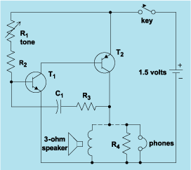
schematic diagram graphic arts
Schematic diagram. A presentation of the element-by-element relationship of all parts of a system.
A schematic diagram serves as a crucial tool in electronic design and engineering, representing the interconnections and relationships between various components within a system. It provides a...
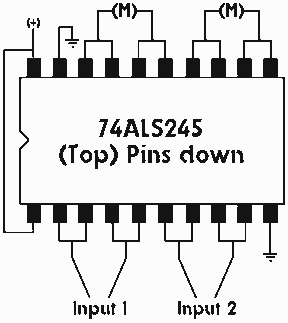
Single IC chip Motor Driver for robots
A motor driver is required in pretty much all walkers including all of my CW series walkers. You need to use it any time you need to supply more current to the motors because the circuit can't supply enough. This...

simplest smf automotive battery charger
A simple battery charger circuit is described, utilizing a single transistor for voltage detection and automatically disconnecting the battery from the supply when fully charged. The circuit's high voltage trip point is set to switch off the charging voltage when...

ELECTRONIC SCHEMATIC CIRCUIT DIAGRAMS
Electronic Schematic Circuit Diagrams Manual PDF Download.
The document provides a comprehensive manual that focuses on electronic schematic circuit diagrams. These diagrams are essential tools for understanding and designing electronic circuits, offering visual representations of circuit components and their interconnections. The...
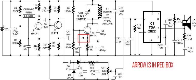
metal detector project circuit
A schematic diagram for a metal detector has been found. The project does not need to be original and can be sourced from the internet. There are several questions regarding this schematic. One query pertains to a small arrow connected...

Big Trak Motor Driver Schematic
Schematic of Big Trak's motor driver circuit. The toy includes 9112 and 9113 transistors (and sometimes 2N6715) because the 75494 chip cannot supply enough current to run the Big Trak's motors by itself.
The motor driver circuit for the Big Trak...
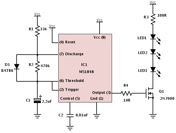
Building a device from a schematic
A common issue encountered is that individuals possess a schematic, also known as a circuit diagram, that they wish to construct. However, they discover that there are...
Building a circuit from a schematic requires a clear understanding of the components involved...

Custom Motor Driver
This chapter was removed from Applied Robotics 2 due to space constraints. It addresses general motor control issues and details the construction of a 5-amp motor driver. The principles discussed can be applied to larger motor controllers. Although commercially available...

Automotive Electrical Tester
This compact tester is designed for checking vehicle electrical circuits. Two LEDs indicate whether one of the clips is connected to the positive supply line (red) or to ground (green). The unit is powered by the vehicle battery. It is...