


Brushless DC motor control circuit
#brushless DC motor
#MC33035
#MC33039
#motor driver
#control circuit
#PWM
#speed control
#hall effect sensor
#BLDC
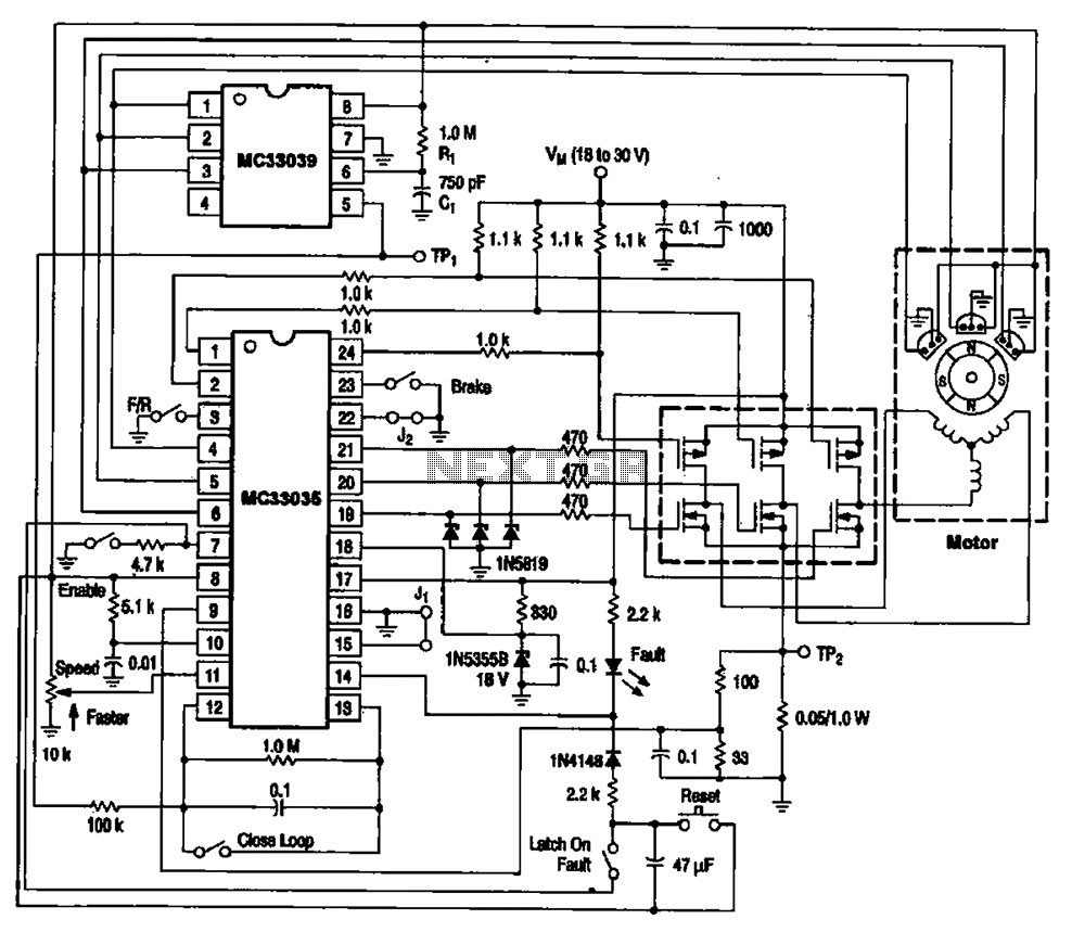
Description: The brushless DC motor control circuit utilizing the MC33035 and MC33039 chips employs a combination of control circuits as illustrated in the figure. The primary components include the MC33035 motor control chip, the MC33039 brushless motor adapter, field effect transistors, and other elements forming the drive circuit. During operation, the MC33035 generates six I-WM signals to drive the motor control circuit through six field effect transistors. This configuration forms a bridge circuit where the outputs are connected to the three-phase motor windings. The three-phase current in the windings changes sequentially according to a specific pattern, creating a rotating magnetic field that causes the rotor of the motor to rotate continuously.
The brushless DC motor control circuit is designed to efficiently manage the operation of brushless motors, which are known for their high efficiency and reliability. The MC33035 serves as the primary control unit, generating pulse-width modulation (PWM) signals that regulate the speed and torque of the motor. The MC33039 complements this functionality by providing additional control features, such as over-current protection and thermal shutdown.
In the circuit, the six field effect transistors (FETs) are configured in a three-phase bridge arrangement, allowing for precise control of the current flowing through each motor winding. The sequential activation of the FETs is crucial for generating a rotating magnetic field. This field interacts with permanent magnets on the rotor, resulting in continuous rotation.
The design of this circuit is particularly beneficial for applications requiring precise speed control and high torque at low speeds. Furthermore, the integration of the MC33035 and MC33039 offers a compact solution that minimizes component count while maximizing performance. The use of FETs ensures rapid switching times and high efficiency, contributing to the overall effectiveness of the motor control system.
In summary, the brushless DC motor control circuit utilizing the MC33035 and MC33039 chips provides a sophisticated solution for controlling brushless motors, ensuring efficient operation and precise control through a well-designed arrangement of power electronics. Brushless DC motor control circuit MC33035 and MC33039 uses a combination of the control circuit is shown in Figure A typical brushless DC motor control circuit, which is mainl y driven by the motor control chip MC33035 and MC33039 brushless motor adapter and field effect transistors and other parts of the drive circuit. At work. MC33035 output channel 6 I-WM signals to drive the motor driving circuit 6 by a field effect transistor.
It is seen from six field effect transistor bridge circuit. Outputs are connected to the three-phase motor winding. Three-phase current in the windings sequentially changed according to the law, to form a rotating magnetic field, the rotor of the drive motor continuously rotates.
The brushless DC motor control circuit is designed to efficiently manage the operation of brushless motors, which are known for their high efficiency and reliability. The MC33035 serves as the primary control unit, generating pulse-width modulation (PWM) signals that regulate the speed and torque of the motor. The MC33039 complements this functionality by providing additional control features, such as over-current protection and thermal shutdown.
In the circuit, the six field effect transistors (FETs) are configured in a three-phase bridge arrangement, allowing for precise control of the current flowing through each motor winding. The sequential activation of the FETs is crucial for generating a rotating magnetic field. This field interacts with permanent magnets on the rotor, resulting in continuous rotation.
The design of this circuit is particularly beneficial for applications requiring precise speed control and high torque at low speeds. Furthermore, the integration of the MC33035 and MC33039 offers a compact solution that minimizes component count while maximizing performance. The use of FETs ensures rapid switching times and high efficiency, contributing to the overall effectiveness of the motor control system.
In summary, the brushless DC motor control circuit utilizing the MC33035 and MC33039 chips provides a sophisticated solution for controlling brushless motors, ensuring efficient operation and precise control through a well-designed arrangement of power electronics. Brushless DC motor control circuit MC33035 and MC33039 uses a combination of the control circuit is shown in Figure A typical brushless DC motor control circuit, which is mainl y driven by the motor control chip MC33035 and MC33039 brushless motor adapter and field effect transistors and other parts of the drive circuit. At work. MC33035 output channel 6 I-WM signals to drive the motor driving circuit 6 by a field effect transistor.
It is seen from six field effect transistor bridge circuit. Outputs are connected to the three-phase motor winding. Three-phase current in the windings sequentially changed according to the law, to form a rotating magnetic field, the rotor of the drive motor continuously rotates.

Quadruple semi-continuous casting machine speed control circuit
The circuit encompasses a main circuit, a trigger circuit, speed negative feedback, negative feedback differential voltage, a current cut-off circuit, loss of field protection, and other components. Given that the motor power is small (1.1 kW), a single-phase circuit is...

Motor speed controller with timer 555
Pulse width modulation (PWM) is a technique to control analog circuits with a digital output. PWM is used in many applications, especially to control light intensity and speed on motors. A PWM circuit makes a square wave with a variable...

PWM DC motor speed control circuit
The circuit operates using pulse position modulation, which is a method distinct from the more commonly utilized pulse width modulation for speed control. A 555 timer is employed as a square wave modulator, generating output pulses with a fixed width...

A control circuit reversing braking and reverse grading speed control function
The circuit depicted in Figure 3-168 utilizes a controller for speed grading and reversing control. A reverse brake is connected to the rotor circuit through an overcurrent relay, labeled KI, for control. The current relay KIi to KI3 serves as...

PWM Motor Speed Control Using Class D Audio Amplifier
This is a Class D audio amplifier circuit that is used to control PWM motor speed. This circuit has two advantages for battery-powered portable devices. First,
The Class D audio amplifier circuit is designed to efficiently manage the speed of...

Custom Motor Driver
This chapter was removed from Applied Robotics 2 due to space constraints. It addresses general motor control issues and details the construction of a 5-amp motor driver. The principles discussed can be applied to larger motor controllers. Although commercially available...

Motor Speed Control Using PWM
Pulse width modulation, commonly referred to as PWM, is utilized to regulate the power supplied to a load without sacrificing efficiency. This technique is often employed in controlling the speed of an electric motor.
PWM operates by varying the width of...
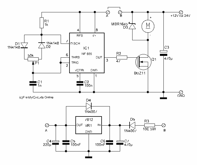
Motor Control circuit II
This circuit is 12 volt motors and lights well regulated. The scheme operates with PWM (Pulse Width Modulation). By IC1, a 555 is a square wave generated by a controllable duty cycle. This means that the width of the pulse...

PWM Motor Speed Control Circuit with Diagram for DC Motor
A simple PWM motor speed control circuit with a diagram and schematic for low power DC motors. This easy-to-make PWM DC motor controller is created using the IC CD40106B.
The PWM (Pulse Width Modulation) motor speed control circuit utilizes the CD40106B...