


Composition 555 motor automatic governor circuit diagram
#555 timer
#motor governor
#flip-flop
#sampling circuit
#switch tube
#automatic control
#RP1
#R7
#DC motor

Description: The circuit consists of a 555 motor automatic governor configuration. It includes flip-flops, a 555 timer, and a switching tube. A sampling circuit is formed by connecting R7 and the motor in series. RP1 is used to control the 555 timer for adjusting the trigger level, which allows for the adjustment of trigger sensitivity.
The described circuit utilizes the 555 timer in a motor control application, functioning as an automatic governor. The 555 timer is a versatile integrated circuit commonly used for timing and pulse generation. In this configuration, it operates in a feedback loop with a sampling circuit formed by the resistor R7 and the motor. The motor's operation is monitored through this sampling circuit, enabling the circuit to regulate the motor's speed based on predefined thresholds.
The flip-flops included in the circuit serve to maintain the state of the motor control, ensuring that the motor operates within the desired parameters. The switching tube acts as a control element that can either allow or cut off power to the motor, depending on the output from the 555 timer and the state of the flip-flops.
Adjustment of the trigger sensitivity is achieved through the variable resistor RP1. By altering the resistance, the voltage level at which the 555 timer triggers can be fine-tuned, allowing for precise control over the motor's response to changes in load or speed. This feature is particularly useful in applications where motor performance needs to be optimized for varying operational conditions.
Overall, this automatic governor circuit exemplifies an effective method for managing motor speed and performance, leveraging the capabilities of the 555 timer, flip-flops, and additional components to create a responsive and adjustable control system. As shown is composed of 555 motor automatic governor circuit. The circuit composed of flip-flops 555 and a switch tube. R7 and motor in series to form a sampling circuit. RP1 c ontrol 555 for adjusting the trigger level, ie adjust the trigger sensitivity.
The described circuit utilizes the 555 timer in a motor control application, functioning as an automatic governor. The 555 timer is a versatile integrated circuit commonly used for timing and pulse generation. In this configuration, it operates in a feedback loop with a sampling circuit formed by the resistor R7 and the motor. The motor's operation is monitored through this sampling circuit, enabling the circuit to regulate the motor's speed based on predefined thresholds.
The flip-flops included in the circuit serve to maintain the state of the motor control, ensuring that the motor operates within the desired parameters. The switching tube acts as a control element that can either allow or cut off power to the motor, depending on the output from the 555 timer and the state of the flip-flops.
Adjustment of the trigger sensitivity is achieved through the variable resistor RP1. By altering the resistance, the voltage level at which the 555 timer triggers can be fine-tuned, allowing for precise control over the motor's response to changes in load or speed. This feature is particularly useful in applications where motor performance needs to be optimized for varying operational conditions.
Overall, this automatic governor circuit exemplifies an effective method for managing motor speed and performance, leveraging the capabilities of the 555 timer, flip-flops, and additional components to create a responsive and adjustable control system. As shown is composed of 555 motor automatic governor circuit. The circuit composed of flip-flops 555 and a switch tube. R7 and motor in series to form a sampling circuit. RP1 c ontrol 555 for adjusting the trigger level, ie adjust the trigger sensitivity.

555 Overheat Detector Alarm Switch
The overhead detector (fire alarm) circuit utilizes a precision integrated temperature sensor, the LM35 (IC1), which offers an accurate linear output.
The overhead detector circuit is designed to monitor ambient temperature levels for fire detection purposes. The core component of this...

Electronic Roulette wheel with 20 LEDs and with 36 LEDs
In this electronic roulette wheel, the 555 timer functions as a pulse generator with a fading frequency. The 4017 counter activates LEDs sequentially in the selected string, while a D-type flip-flop (4013 IC) serves as a divider by two to...

555 multi-purpose repair circuit diagram
The overhaul includes features such as online judge diodes, the ability to test whether transistors are functioning properly, and the capability to assess TTL logic levels or high impedance states. It can output signals at 37 MHz, bar television signals...

Capacitance Meter
The 555 timer IC serves as the core component of the circuit, tasked with charging an unknown capacitor (Cx) to a predetermined voltage. Following this, the capacitor discharges into a meter circuit, which measures the current flowing through a 47-ohm...

TV REMOTE JAMMER CIRCUIT USING 555 TIMER
A TV remote jammer circuit using the NE555 timer IC. This device allows users to watch their favorite TV channels without interruptions, as it prevents others from changing the channel using a remote control when the circuit is activated. The...

dc motor control circuit
S1 and S2 are normally open, push-to-close, momentary switches. The diodes can be red or green and serve solely as indicators for direction. The TIP31 transistors may need to be adjusted based on the motor specifications. It is important to...

555 ASTABLE_FREQUENCY METER
The circuit illustrated is a straightforward digital frequency meter that displays the frequency in hertz of an astable 555 timer. It may potentially be modified for alternative applications. An NPN transistor, TR2, is linked to the 555 astable timer being...

555 / 556 H bridge
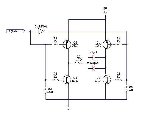
A low power H-bridge may be necessary for driving a motor. The 555 integrated circuit (IC) can handle a load of up to 200 mA, either sourcing or sinking, making it a potential driver if the output can be controlled...
When page is bookmarked text here is referenced verbatim
The image shows a completed locked anti-phase motor controller built on a breadboard, utilizing general-purpose transistors to control small DC motors for robotics applications. A typical DC motor controller lacks a braking function, which is essential for precise control. Addressing...