


Construction and operation of the brushless motor windings principle e
#brushless motor
#windings
#triangular coils
#motor control
#switching
#construction
#working principle
#electrical engineering

Description: The construction and operation of brushless motor windings are based on the principle of triangular coils. Through the switch, the stator coil current can be cycled, resulting in the formation of a rotating magnetic field. The cycle of the current and the state of the switch path can be observed from the figure. This switching is typically managed by a transistor, and to achieve a smooth transition, a drive control circuit is necessary.
The brushless motor operates by utilizing a series of windings arranged in a specific configuration, often triangular, which allows for efficient electromagnetic interaction. The stator is equipped with multiple coils that are energized in a precise sequence to create a rotating magnetic field. This field interacts with the rotor, inducing motion without the need for brushes, which are commonly found in traditional DC motors.
The switching mechanism is crucial for the operation of the motor. It typically involves a series of power transistors that act as electronic switches to control the current flowing through the motor windings. The drive control circuit manages the timing and sequence of these switches, ensuring that the current flows through each winding in a controlled manner. This sequence must be synchronized with the rotor's position to maintain efficient operation and minimize energy loss.
A feedback system, often using sensors such as Hall effect sensors or encoders, provides information about the rotor's position to the control circuit. This feedback allows for precise adjustments to the switching sequence, enhancing the motor's performance and responsiveness.
In summary, the brushless motor's design, with its triangular coil structure and sophisticated control mechanisms, enables high efficiency and reliability in various applications, ranging from consumer electronics to industrial machinery. The combination of electronic switching and feedback control systems plays a pivotal role in ensuring optimal operation and performance.Construction and operation of the brushless motor windings principle e Structure and working principle of the triangular coils As shown, through the switch, you can make the st ator coil current cycle turned, and the formation of a rotating magnetic field. Can be seen from the figure, the cycle of the week and the current state of the switch path. Is usually caused by switching of the switching transistor, the switch in order to achieve an orderly transition must have a drive control circuit.
The brushless motor operates by utilizing a series of windings arranged in a specific configuration, often triangular, which allows for efficient electromagnetic interaction. The stator is equipped with multiple coils that are energized in a precise sequence to create a rotating magnetic field. This field interacts with the rotor, inducing motion without the need for brushes, which are commonly found in traditional DC motors.
The switching mechanism is crucial for the operation of the motor. It typically involves a series of power transistors that act as electronic switches to control the current flowing through the motor windings. The drive control circuit manages the timing and sequence of these switches, ensuring that the current flows through each winding in a controlled manner. This sequence must be synchronized with the rotor's position to maintain efficient operation and minimize energy loss.
A feedback system, often using sensors such as Hall effect sensors or encoders, provides information about the rotor's position to the control circuit. This feedback allows for precise adjustments to the switching sequence, enhancing the motor's performance and responsiveness.
In summary, the brushless motor's design, with its triangular coil structure and sophisticated control mechanisms, enables high efficiency and reliability in various applications, ranging from consumer electronics to industrial machinery. The combination of electronic switching and feedback control systems plays a pivotal role in ensuring optimal operation and performance.Construction and operation of the brushless motor windings principle e Structure and working principle of the triangular coils As shown, through the switch, you can make the st ator coil current cycle turned, and the formation of a rotating magnetic field. Can be seen from the figure, the cycle of the week and the current state of the switch path. Is usually caused by switching of the switching transistor, the switch in order to achieve an orderly transition must have a drive control circuit.

Motor control circuit for forward and reverse phase induction
This is the power diagram for motor forward and reverse operation. To change the motor direction, one polarity must be altered, for example, changing R to S. For detailed information, please refer to the following.
The described power diagram illustrates a...

Motorized Video Camera Mount
The camera rotator circuit utilizes a 2716 EPROM to store a logic value table that governs the motor driver (H-bridge) circuit. The schematic illustrates the EPROM data. By employing the EPROM, a significant number of discrete gates are eliminated. The...

motor timer
The primary concept is to rotate the motor slightly every 15 seconds. A monofilament line conveys the motion to the ornament, which is wound by the motor and gradually unwinds as the ornament turns. The charging circuit includes a 1...

Structure and working principle of brushless motor windings
The structure and working principle of brushless motor windings involve the triangular coil configuration. The stator coil can be activated through a switch, resulting in the generation of a rotating magnetic field. The cycling of current and the state of...

Motor control with tachometer
The generator output is rectified, filtered, and applied between the positive supply voltage and the base of the detector transistor. This configuration provides a negative voltage that reduces the base voltage as the speed increases. During normal operation, if the...

High-performance power supply LM334
The circuit functions as a switching power supply designed to operate alongside a linear regulated power supply. Key characteristics include high efficiency and low dropout voltage. It effectively filters out high-frequency ripple voltage and manages instantaneous voltage variations, making it...

Radio Buttons Using Push On Switch Latching Circuit
This is a switching circuit that provides a latching mechanism to create a set of radio buttons using push buttons. This circuit consists of an interlocking circuit.
The switching circuit operates on the principle of latching, allowing multiple push buttons to...
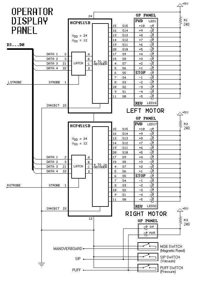
Dual-Motor SIP&PUFF Controlled Kayak System
The YouTube video below demonstrates the quick and easy setup of the system at the launch site.
The provided description indicates a focus on the efficiency of system installation at a launch site, as showcased in a YouTube video. In an...

LMZ13608 8A switching power supply circuit design
A simple, high-efficiency switching power supply circuit can be designed using the LMZ13608 8A regulator. This regulator offers very high efficiency and requires few external components. It supports a wide input voltage range of 6 to 36 volts and provides...