


Controlling Stepper Motor with a Parallel Port
#stepper motor
#parallel port
#computer control
#robotics
#PCB drilling
#camera panning
#automation
#unipolar motor

Description: This is an easy to build stepper motor driver that will allow you to precisely control a unipolar stepper motor through your computer's parallel port. With a stepper motor you can build a lot of interesting gadgets such as robots, elevator, PCB drilling mill, camera panning system, automatic fish feeder, etc. If you have never worked with stepper motors before you will surely have a lot of fun with this project. More: Stepper motors are very different from regular DC motors. Instead of spinning like DC motors do, stepper motors step at a specific resolution for each pulse. The motor that we are using needs 48 steps/pulses just to complete a single revolution!
The stepper motor driver circuit described is designed to interface a unipolar stepper motor with a computer's parallel port, enabling precise control over the motor's movement. This circuit typically includes a microcontroller or a dedicated driver IC that interprets the signals from the parallel port and converts them into the necessary control signals for the stepper motor.
The unipolar stepper motor operates by energizing its coils in a specific sequence, allowing it to move in discrete steps. Each pulse sent from the parallel port corresponds to one step of the motor. The circuit may consist of several components, including transistors or MOSFETs to switch the motor coils on and off, resistors to limit current, and diodes for flyback protection to prevent voltage spikes when the coils are de-energized.
For a typical unipolar stepper motor requiring 48 steps per revolution, the driver circuit must generate a sequence of 48 pulses to complete one full rotation. The software on the computer side will need to be programmed to send these pulses in the correct order and timing to achieve smooth and controlled motion.
The driver circuit may also include a power supply section to provide the necessary voltage and current levels for the stepper motor's operation, as unipolar stepper motors often require higher voltages compared to the logic levels used by the parallel port.
Overall, the project presents an excellent opportunity for experimentation and learning, allowing users to explore robotics and automation applications through the controlled movement of stepper motors.This is an easy to build stepper motor driver that will allow you to precisely control a unipolar stepper motor through your computer`s parallel port. With a stepper motor you can build a lot of interesting gadgets such as robots, elevator, PCB drilling mill, camera panning system, automatic fish feeder, etc.
If you have never worked with stepper motors before you will surely have a lot of fun with this project. Stepper motors are very different from a regular DC motors. Instead of spinning like DC motors do, stepper motor steps at a specific resolution for each pulse. The motor that we are using needs 48 steps / pulses just to complete a single revolution! That
The stepper motor driver circuit described is designed to interface a unipolar stepper motor with a computer's parallel port, enabling precise control over the motor's movement. This circuit typically includes a microcontroller or a dedicated driver IC that interprets the signals from the parallel port and converts them into the necessary control signals for the stepper motor.
The unipolar stepper motor operates by energizing its coils in a specific sequence, allowing it to move in discrete steps. Each pulse sent from the parallel port corresponds to one step of the motor. The circuit may consist of several components, including transistors or MOSFETs to switch the motor coils on and off, resistors to limit current, and diodes for flyback protection to prevent voltage spikes when the coils are de-energized.
For a typical unipolar stepper motor requiring 48 steps per revolution, the driver circuit must generate a sequence of 48 pulses to complete one full rotation. The software on the computer side will need to be programmed to send these pulses in the correct order and timing to achieve smooth and controlled motion.
The driver circuit may also include a power supply section to provide the necessary voltage and current levels for the stepper motor's operation, as unipolar stepper motors often require higher voltages compared to the logic levels used by the parallel port.
Overall, the project presents an excellent opportunity for experimentation and learning, allowing users to explore robotics and automation applications through the controlled movement of stepper motors.This is an easy to build stepper motor driver that will allow you to precisely control a unipolar stepper motor through your computer`s parallel port. With a stepper motor you can build a lot of interesting gadgets such as robots, elevator, PCB drilling mill, camera panning system, automatic fish feeder, etc.
If you have never worked with stepper motors before you will surely have a lot of fun with this project. Stepper motors are very different from a regular DC motors. Instead of spinning like DC motors do, stepper motor steps at a specific resolution for each pulse. The motor that we are using needs 48 steps / pulses just to complete a single revolution! That

CoSaTrak drive satellite tracking circuit
The back EMF voltage spikes produced by stepper motors, especially higher voltage motors, can damage a PC's printer port if connections are made incorrectly, flyback diodes are absent, or connected in reverse. The safest options are opto-isolated or buffered/inverted circuits....

Digital Encoder Circuit diagram Using Stepper Motor
The circuit illustrated in the schematic diagram below allows for the visualization of the direction and shaft rotation of a stepper motor on an LED display. Instead of utilizing a digital rotation encoder as an input, this circuit employs a...

stepper ttl
The schematic illustrates the electronics needed to control a stepper motor. It primarily consists of three commonly available integrated circuits and four power transistors for complete motor control. Four PNP power transistors amplify the weak electronic signals into sufficient current...

Stepper Motor Interface to Microcontroller
The circuit features four pins labeled "Controller pin 1," "Controller pin 2," "Controller pin 3," and "Controller pin 4," which are responsible for controlling the motion and direction of the stepper motor based on the step sequence programmed into the...
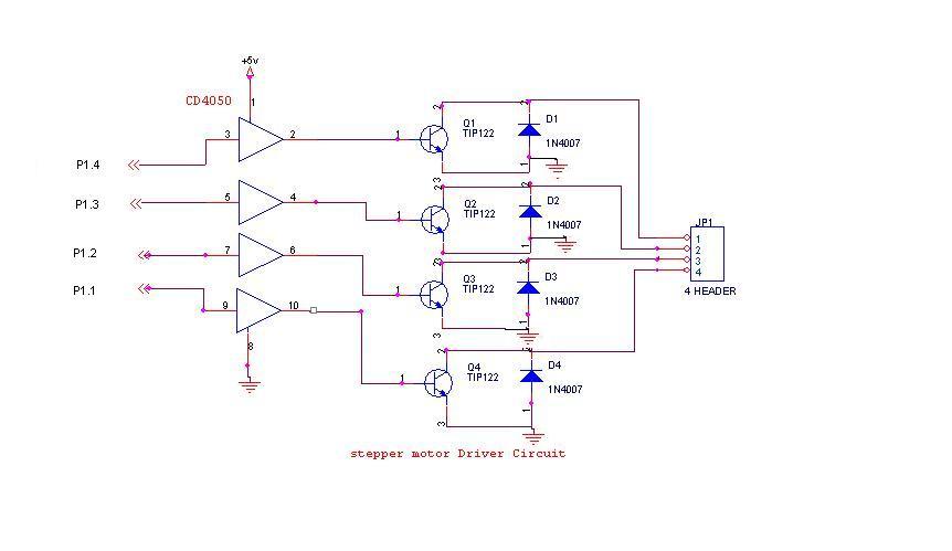
Stepper Motor Controller Schematic
A 6V, 2A stepper motor is utilized in this circuit. The CD4050 hex buffer is employed to connect to the microcontroller. The output of the CD4050 is linked to the base of a TIP122 transistor. The emitter and collector of...

Two Wires-Stepper Motor Controller
To achieve a low-cost, accurate, and simple position control system, a stepper motor can be utilized. A circuit designed to drive the motor should be mounted in proximity to the motor itself.
Stepper motors are widely employed in applications requiring precise...

Stepper Motor Control Circuit
This circuit is not visually appealing nor easy to implement, requiring considerable effort. The stepper motor consists of two coils, necessitating the use of two LMD18245 chips to manage the current flow through these coils. It is noteworthy that motor...
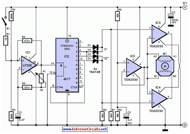
Stepper Motor Controller
Stepper motors are available in several versions and sizes with a variety of operating voltages. The advantage of this general-purpose controller is that...
Stepper motors are electromechanical devices that convert electrical energy into precise mechanical movement. They are widely used in...

RS 422 Compatible Indicator
The design involves creating a circuit and programming for a stepper motor controller, developing a speed-controlled DC motor circuit for the propulsion system of the project, and designing a navigation system using a MEMS accelerometer circuit. This section deviates slightly...