


DC Chopper control vs Phase Angle control
#DC chopper
#phase angle control
#triac
#motor driver
#control methods
#design trade-offs
#motor speed
#power electronics
#industrial applications

Description: The two most common motor control methods are DC Chopper control and Phase Angle control. This article explores the differences between the two methods, identifying some key trade-offs that can be useful for motor control designers when determining the best control method to use for their specific application. Shown in Figures 1 and 6, respectively, are the triac control and chopper control circuits used to drive a universal motor in a simple household appliance. The main difference is that the triac and Gate Drive Transistor in the Phase Angle control circuit are replaced by an IGBT. The chopper circuit also introduces a full-wave rectifier to the AC line circuit because the IGBT only conducts current in one direction. The main principle behind the Phase Angle control circuit is that a microcontroller (MCU) is used to vary the firing angle to the triac. By adjusting the firing angle to the triac, that is, the point in the AC voltage waveform where the triac turns on, the voltage applied to the motor can be modulated, and the speed of the motor can be regulated. The firing angle of the triac is referenced to the zero crossing of the AC waveform, which is sensed using a zero crossing detect circuit on the line voltage. The MCU employs a special timer that emits a series of one-shot pulses into the gate of the triac to turn it on. A series of pulses is recommended as opposed to just a single pulse per cycle because the motor is an inductive load, and a pulse train ensures the triac conducts current in both positive and negative directions. An illustration of this principle can be seen in Figures 2 and 3. In Figure 2, the gate pulses to the triac are for roughly one-third of the duty cycle of the voltage waveform, during which the triac is conducting. In laboratory tests, this combination of voltage and firing angle resulted in a motor speed of 900 RPM. In Figure 3, more gate pulses result in a larger firing angle and a longer period in which the triac is conducting, yielding a motor speed of 16,000 RPM. Since the AC voltage waveform operates at 60 Hz, it is noteworthy that the firing angle is applied 120 times a second due to two zero crossings per cycle. There is no linear relationship between torque and AC current, making a closed-loop control scheme for controlling torque impractical in this case. In the laboratory tests, an R8C MCU from Renesas Electronics was used to implement the control algorithm for both control methods. As noted in Figure 4, the device offers several 8-bit and 16-bit timers that can be configured to perform various functions such as triac and chopper control, for instance, matching triacs rated at 20 and 25 amps for the phase-angle circuit or IGBTs rated at 45 and 60 amps for DC chopper control. Timer RB of the Renesas MCU is an 8-bit timer with an 8-bit prescaler that can implement a general-purpose timer or waveform generator. The general-purpose timer is used to determine the time between two consecutive Hall sensor signals to determine speed. Timer RC is a 16-bit timer that can be configured as an input capture, output compare, or PWM generator. This timer generates the required PWM with accurate timings to fire the TRIAC or the DC Chopper. Timer RD is an advanced 16-bit timer capable of generating PWM individually from each output pin or creating up to three complementary PWM pairs with automatic dead time insertion. This timer is typically used to control the H-bridge implementation (equivalent to the DC Chopper circuit) when the motor is rotated in both directions. In this article, the motor is rotating in one direction only.
The motor control system described involves two primary techniques: DC Chopper control and Phase Angle control, each with distinct operational characteristics and applications. The Phase Angle control method utilizes a triac, which is triggered at a specific angle of the AC waveform, allowing for variable voltage and speed control of the motor. The zero crossing detection circuit plays a crucial role in timing the firing of the triac, ensuring that the control is synchronized with the AC line frequency. The use of a microcontroller allows for precise adjustments to the firing angle, enabling effective modulation of the motor speed.
In contrast, the DC Chopper control method employs an IGBT and a full-wave rectifier, which is essential for converting AC input to a controlled DC output. This method is particularly advantageous in applications requiring high efficiency and precise control over the motor's performance. The IGBT's unidirectional conduction necessitates the inclusion of a rectifier to facilitate the proper operation of the motor.
The choice between these two control methods depends on the specific application requirements, including the desired speed range, efficiency, and control complexity. The laboratory tests conducted with the Renesas R8C MCU demonstrate the effectiveness of both methods, highlighting the MCU's capability to handle various timer configurations for optimal control. The implementation of PWM signals through the timers allows for accurate control of the triac or IGBT, ensuring that the motor operates effectively across different speeds.
In summary, the integration of these control methods within a microcontroller-based system provides a flexible and efficient solution for motor control in household appliances, with the potential for further optimization based on specific design criteria. The detailed analysis of the firing angles, pulse widths, and timer configurations illustrates the complexity and sophistication involved in modern motor control systems.The two most common motor-control methods are: DC Chopper control and Phase Angle control. This article explores the differences between the two methods, identifying some of the key trade-offs that can be useful for motor-control designers when determining which is the best control method to use for their specific application. Shown in Figures 1 and 6, respectively, the triac control and chopper control circuits used to drive the universal motor can be used in a very simple household appliance. The main difference is that the triac and Gate Drive Transistor in the Phase Angle control circuit are replaced by an IGBT.
The chopper circuit also introduces in a full-wave rectifier to the AC line circuit because the IGBT only conducts current in one direction. The main principle behind the Phase Angle control circuit is that the microcontroller (MCU) is used to vary the firing angle to the triac.
By adjusting the firing angle to the triac, i. e. , the point in the AC voltage waveform where the triac turns on, the voltage applied to the motor can be modulated and the speed of the motor can be regulated. The firing angle of the triac is referenced to the zero crossing of the AC waveform, which is sensed using a zero crossing detect circuit on the line voltage.
The MCU uses a special timer that emits a series of one-shot pulses into the gate of the triac to turn it on. A series of pulses are recommended as opposed to just a single pulse per cycle, because the motor is an inductive load, and a pulse train ensures the triac conducts current in both positive and negative directions.
An illustration of this principle can be seen in Figures 2 and 3. In Figure 2, the gate pulses to the triac are for roughly one third of the duty cycle of the voltage waveform. The triac is conducting during this time. In the laboratory, where this data was collected, this combination of voltage and firing angle resulted in a motor speed of 900 RPM.
In Figure 3, there are more gate pulses resulting in a larger firing angle and a longer period in which the triac is conducting. With this firing angle, the resulting motor speed is 16, 000 RPM. Since the AC voltage waveform is 60 Hz, it is worth noting that the firing angle is applied 120 times a second, because there are two zero crossings per cycle.
There is no linear relationship between torque and AC current, so a closed-loop control scheme for controlling torque is not practical, nor does it make sense in this case. In the laboratory tests, an R8C MCU from Renesas Electronics was used to implement the control algorithm for both control methods.
As noted in Figure 4, the device offers a number of 8-bit and 16-bit timers that can be configured to perform a variety of functions such as triac and chopper control, for instance matching to triacs rates at 20 and 25 amps for phase-angle circuit or to IGBTs rated at 45 and 60 amps for DC chopper control. Timer RB of the Renesas MCU is an 8-bit timer with an 8-bit pre-scalar that can implement a general-purpose timer or waveform generator.
The general purpose timer is used to determine the time between two consecutive Hall sensor signals to determine the speed. Timer RC is a 16-bit timer which can be configured as an input capture, output compare or PWM generator.
This timer is used to generate required PWM with accurate timings to fire the TRIAC or the DC Chopper. Timer RD is an advanced 16-bit timer that can generate PWM individually out of each of the output pins or generate up to three complementary PWM pairs with automatic dead time insertion.
This timer is typically used to control the H-bridge implementation (equivalent of DC Chopper circuit) when the motor is also rotated in both directions. In this article, motor is rotating only in one
The motor control system described involves two primary techniques: DC Chopper control and Phase Angle control, each with distinct operational characteristics and applications. The Phase Angle control method utilizes a triac, which is triggered at a specific angle of the AC waveform, allowing for variable voltage and speed control of the motor. The zero crossing detection circuit plays a crucial role in timing the firing of the triac, ensuring that the control is synchronized with the AC line frequency. The use of a microcontroller allows for precise adjustments to the firing angle, enabling effective modulation of the motor speed.
In contrast, the DC Chopper control method employs an IGBT and a full-wave rectifier, which is essential for converting AC input to a controlled DC output. This method is particularly advantageous in applications requiring high efficiency and precise control over the motor's performance. The IGBT's unidirectional conduction necessitates the inclusion of a rectifier to facilitate the proper operation of the motor.
The choice between these two control methods depends on the specific application requirements, including the desired speed range, efficiency, and control complexity. The laboratory tests conducted with the Renesas R8C MCU demonstrate the effectiveness of both methods, highlighting the MCU's capability to handle various timer configurations for optimal control. The implementation of PWM signals through the timers allows for accurate control of the triac or IGBT, ensuring that the motor operates effectively across different speeds.
In summary, the integration of these control methods within a microcontroller-based system provides a flexible and efficient solution for motor control in household appliances, with the potential for further optimization based on specific design criteria. The detailed analysis of the firing angles, pulse widths, and timer configurations illustrates the complexity and sophistication involved in modern motor control systems.The two most common motor-control methods are: DC Chopper control and Phase Angle control. This article explores the differences between the two methods, identifying some of the key trade-offs that can be useful for motor-control designers when determining which is the best control method to use for their specific application. Shown in Figures 1 and 6, respectively, the triac control and chopper control circuits used to drive the universal motor can be used in a very simple household appliance. The main difference is that the triac and Gate Drive Transistor in the Phase Angle control circuit are replaced by an IGBT.
The chopper circuit also introduces in a full-wave rectifier to the AC line circuit because the IGBT only conducts current in one direction. The main principle behind the Phase Angle control circuit is that the microcontroller (MCU) is used to vary the firing angle to the triac.
By adjusting the firing angle to the triac, i. e. , the point in the AC voltage waveform where the triac turns on, the voltage applied to the motor can be modulated and the speed of the motor can be regulated. The firing angle of the triac is referenced to the zero crossing of the AC waveform, which is sensed using a zero crossing detect circuit on the line voltage.
The MCU uses a special timer that emits a series of one-shot pulses into the gate of the triac to turn it on. A series of pulses are recommended as opposed to just a single pulse per cycle, because the motor is an inductive load, and a pulse train ensures the triac conducts current in both positive and negative directions.
An illustration of this principle can be seen in Figures 2 and 3. In Figure 2, the gate pulses to the triac are for roughly one third of the duty cycle of the voltage waveform. The triac is conducting during this time. In the laboratory, where this data was collected, this combination of voltage and firing angle resulted in a motor speed of 900 RPM.
In Figure 3, there are more gate pulses resulting in a larger firing angle and a longer period in which the triac is conducting. With this firing angle, the resulting motor speed is 16, 000 RPM. Since the AC voltage waveform is 60 Hz, it is worth noting that the firing angle is applied 120 times a second, because there are two zero crossings per cycle.
There is no linear relationship between torque and AC current, so a closed-loop control scheme for controlling torque is not practical, nor does it make sense in this case. In the laboratory tests, an R8C MCU from Renesas Electronics was used to implement the control algorithm for both control methods.
As noted in Figure 4, the device offers a number of 8-bit and 16-bit timers that can be configured to perform a variety of functions such as triac and chopper control, for instance matching to triacs rates at 20 and 25 amps for phase-angle circuit or to IGBTs rated at 45 and 60 amps for DC chopper control. Timer RB of the Renesas MCU is an 8-bit timer with an 8-bit pre-scalar that can implement a general-purpose timer or waveform generator.
The general purpose timer is used to determine the time between two consecutive Hall sensor signals to determine the speed. Timer RC is a 16-bit timer which can be configured as an input capture, output compare or PWM generator.
This timer is used to generate required PWM with accurate timings to fire the TRIAC or the DC Chopper. Timer RD is an advanced 16-bit timer that can generate PWM individually out of each of the output pins or generate up to three complementary PWM pairs with automatic dead time insertion.
This timer is typically used to control the H-bridge implementation (equivalent of DC Chopper circuit) when the motor is also rotated in both directions. In this article, motor is rotating only in one
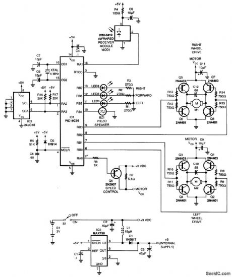
START UP CONTROL
A bidirectional three-layer trigger for a triac allows triggering on both half-cycles, with the activation point determined by a 1-megohm potentiometer setting. The triac's rating dictates the load size it can manage. This circuit combines two functions: it serves as...

Temperature Controller with U217B
A triac controller for switching resistive loads directly from the mains supply using the zero crossing technique. The device is powered directly from the mains via a diode and dropper resistor, and the IC has its own regulator to limit...

A Phase Controlled Triac (HT-32)
The following circuit illustrates a Phase Controlled Triac (HT-32) Circuit Diagram. Features include a simple circuit design, and bilateral triggering diacs provide a...
The Phase Controlled Triac circuit, utilizing the HT-32 component, is designed for applications requiring precise control of AC...
Power Flip Flop Using A Triac
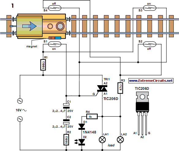
This method can be illustrated using an uncommon semiconductor power flip-flop. A flip-flop is a toggling circuit with two stable states (bistable multivibrator) that retains its output state without an input pulse. Triacs can be used to implement flip-flops when...
Three-Power-Level Triac Controller Circuit
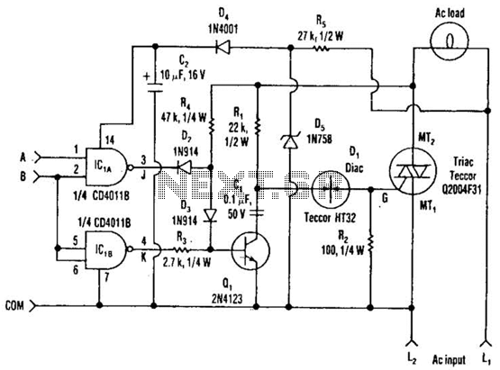
Three power levels are provided by the two logic inputs of this enhanced circuit. R5, D4, D5, and O2 create a power supply for the logic integrated circuit. These components can be excluded if an alternative low voltage source is...

Simple Electronic Fan Regulator Circuit PCB
The circuit diagram presented is a triac-diac electronic fan regulator designed to reduce power consumption of electric fans, even at low speeds. Traditional resistor-inductor fan regulators tend to generate excess heat, wasting energy when the fan operates at lower speeds,...
Zero-point-switching-temperature-control
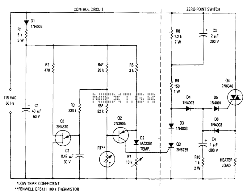
This modulated triac zero-point switching circuit controls heater loads operating from 115 Vac. Circuit operation is best described by splitting the circuit into two parts. The circuit on the right is the zero-point switch; to the left is the proportional...

Triac regulation of mains voltage
Triac regulation is designed to control the power of mains appliances. It can adjust the brightness of incandescent light bulbs, halogen lamps, dimmable energy savers, heaters, and other thermal devices, as well as regulate motors. The power can be easily...

Triac-SCR-Thyristor
A center-tap 50Hz step-down transformer with two diodes is utilized to generate a series of positive sine pulses at 100Hz, which is applied to the base of Q6 through resistor R51. The 2N2646 is a unijunction transistor (UJT) housed in...