


DC fan control circuit for power amplifier Schematic Diagram
#DC fan
#variable speed
#power amplifier
#input signal
#VR1
#speed control
#cooling
#fan rotation
#transformer
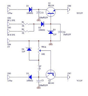
Description: DC fan control circuit for a power amplifier. It features a variable speed DC fan that operates based on the input signal. The speed of the fan's rotation is dependent on the amplitude of the input signal received from the speaker lines. In the absence of a signal, the fan will operate at a slow speed determined by the setting of variable resistor VR1. The input power can be directly sourced from the main transformer, which has a 12V center-tapped configuration, eliminating the need for an additional transformer.
The DC fan control circuit is designed to enhance the cooling efficiency of power amplifiers by modulating the fan speed according to the audio signal levels. The circuit utilizes a variable resistor (VR1) to set a minimum fan speed, ensuring that the fan operates even when there is no significant audio signal, thereby preventing overheating of the amplifier components.
The circuit typically consists of a transistor or operational amplifier configured to sense the input signal from the amplifier's speaker output. As the input signal increases, the transistor or operational amplifier adjusts the voltage applied to the fan, thereby increasing its speed. This response allows for a dynamic cooling solution that adapts to the thermal requirements of the amplifier, improving performance and reliability.
The power supply for this circuit is conveniently derived from the existing transformer used in the amplifier, which provides a 12V center-tapped output. This design choice simplifies the overall circuit layout and reduces component count, making it an efficient solution for integrating fan control into power amplifier systems.
In summary, the DC fan control circuit for a power amplifier is an essential component that not only ensures optimal thermal management but also contributes to the longevity and performance of the audio equipment.DC fan control circuit for power amplifier. Variable speed DC fan This series of works based on the input signal. Speed / fan rotation depending on size of the input signal coming from speaker lines. If there is no signal then the fan will spin slowly according to the setting VR1. Input supply can be taken directly from the main transformer power amplifier, 12V CT 12V, so no need to increase the transformer again. You are reading the Circuits of DC fan control circuit for power amplifier And this circuit permalink url it is
The DC fan control circuit is designed to enhance the cooling efficiency of power amplifiers by modulating the fan speed according to the audio signal levels. The circuit utilizes a variable resistor (VR1) to set a minimum fan speed, ensuring that the fan operates even when there is no significant audio signal, thereby preventing overheating of the amplifier components.
The circuit typically consists of a transistor or operational amplifier configured to sense the input signal from the amplifier's speaker output. As the input signal increases, the transistor or operational amplifier adjusts the voltage applied to the fan, thereby increasing its speed. This response allows for a dynamic cooling solution that adapts to the thermal requirements of the amplifier, improving performance and reliability.
The power supply for this circuit is conveniently derived from the existing transformer used in the amplifier, which provides a 12V center-tapped output. This design choice simplifies the overall circuit layout and reduces component count, making it an efficient solution for integrating fan control into power amplifier systems.
In summary, the DC fan control circuit for a power amplifier is an essential component that not only ensures optimal thermal management but also contributes to the longevity and performance of the audio equipment.DC fan control circuit for power amplifier. Variable speed DC fan This series of works based on the input signal. Speed / fan rotation depending on size of the input signal coming from speaker lines. If there is no signal then the fan will spin slowly according to the setting VR1. Input supply can be taken directly from the main transformer power amplifier, 12V CT 12V, so no need to increase the transformer again. You are reading the Circuits of DC fan control circuit for power amplifier And this circuit permalink url it is

55W (Originally 75W) Power Amplifier
To order boards, click to access the ESP Purchase form. Verify the price and postage, then open the order form, fill it in, and print it from your browser. Boards are sold only as a stereo pair and are supplied...
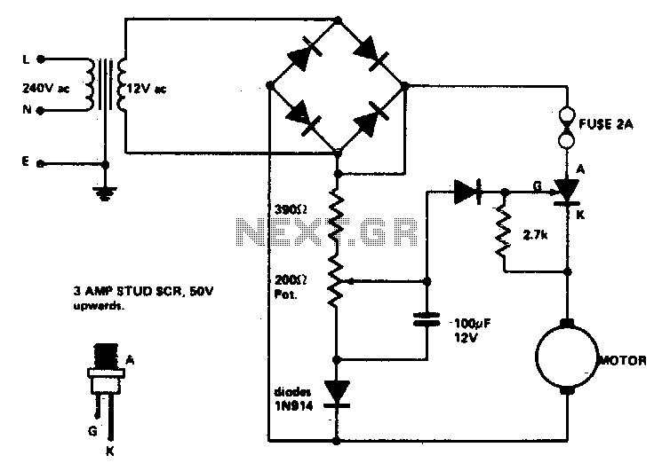
Speed control for model trains or cars
Low voltage speed control provides excellent starting torque and effective speed regulation. Additionally, a reversing switch can be integrated into the motor leads.
Low voltage speed control circuits are essential in applications where precise motor control is required, such as in...

Circuit Diagram Of Power Amplifier Electronic Circuits
The following circuit illustrates a power amplifier electronic circuit, specifically a tube audio RF amplifier circuit diagram. This circuit is based on the LM324 integrated circuit.
The power amplifier circuit utilizing the LM324 operational amplifier is designed to enhance audio signals...

smith kanapadz replication 6
The user intends to purchase a transformer to operate with a 12V battery; however, the transformer in question differs from the one utilized by the user romerouk from Overunity.
The circuit design involves a transformer specifically engineered for low-voltage applications, such...

Schematic Diagram 300W Power Amplifier For Subwoofer
The 300W amplifier circuit presented is a conventional design. It includes connections for the internal SIM and incorporates filtering for RF protection (R1, C2). The input is facilitated through a 4.7µF bipolar capacitor, which offers substantial capacitance in a compact...
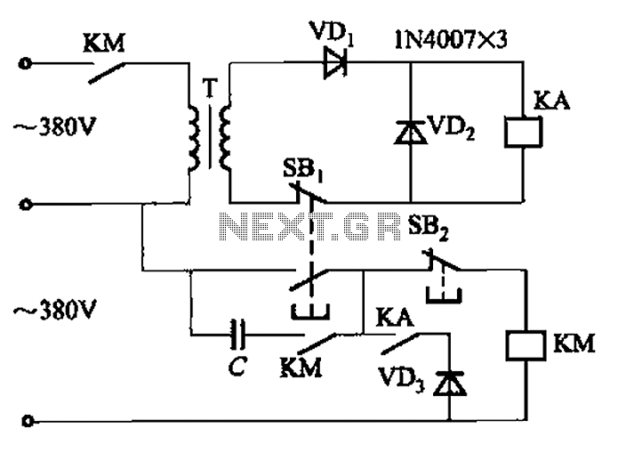
Transformer AC contactor DC operation circuit b
The AC contactor DC transformer circuit operates using various types of transformers and AC contactors in a DC application.
The AC contactor DC transformer circuit is designed to control and manage electrical power in applications where alternating current (AC) is converted...

Compact 100W power amplifier circuit
The pLPC1342V and NE are two companies involved in a tube amplifier circuit utilizing 2SA1227A and 2SC2987A transistors, achieving a maximum output power of up to 120W with a cutoff frequency of up to 500 MHz. The circuit, illustrated in...

Speed-Control Switch Circuit
The speed-control switch provides effective control and stability across its entire operating range. This circuit utilizes two SCR devices arranged in a full-wave configuration to manage the DC power supplied to a motor. A center-tapped transformer is employed to provide...
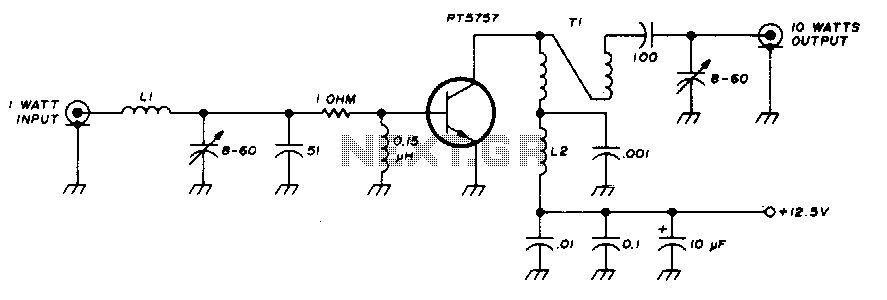
Two-meter 10 watt power amplifier
This 10-watt, 144-MHz power amplifier utilizes a TRW PT5757 transistor. The inductor LI consists of 4 turns of no. 20 enameled wire with a 3/32" inner diameter, while inductor L2 comprises 10 turns of no. 20 enameled wire with the...