


Ed Gray Motor Generator
#high amperage
#spark gap
#high voltage
#glass tubes
#diodes
#triode valves
#switching device
#Nikola Tesla

Description: This type of design can produce a very high amperage current for a fraction of a second that can be used to do some useful work if properly harnessed. The switching device could be a rotating spark gap as used by Nikola Tesla or some high-speed electronic device. It is believed that only glass tubes such as diodes or triode valves are really good at this and not transistors as they cannot handle the high voltage and high current produced in these devices without burning themselves out. As used by Edwin Gray in his invention, the charging circuit is basically a 12-volt battery being driven by vibrating relays to pulse the power through a step-up transformer to raise voltage from 12 volts to approximately 3000 volts. This then is rectified and used to charge a bank of capacitors.
This bank of capacitors is then discharged for a nanosecond period into a specially designed tube which seems nothing more than a copper rod, a spark gap, some carbon, and a series of concentric rings around the spark gap. The resulting power collected on those rings is then fed to the earth via an air induction transformer or to the positive terminal of the charging batteries.
The power appearing at the secondary of this air induction transformer is then used to power the motoring coils of the specially designed motor.
High Voltage Induction Coil
Another method used in early X-ray machines and also by Marconi in his first radio transmission across the Atlantic Ocean was the induction coil, basically two coils wound on a metal rod, a small number of primary windings in heavier gauge wire and a large number of finer gauge winding, basically a step-up transformer using the primary magnetic field to operate a switch that controls the power to the primary winding.
This causes the magnetic field in the primary coil to build up and down, which then causes, by induction, an alternating high voltage output in the secondary coil (most likely a square wave).
Electrostatic generation of high potential.
The people at the Swiss community of Merithnita seem to be using a Wimshurst machine to generate the high voltage needed to run their free energy device. This device was a popular means to generate high voltage in the late 19th century and early 20th century. Its role was at some stage used to provide the high voltage needed for early X-ray machines in hospitals but is usually superseded by modern electronic versions or the Van de Graaf machine in modern physics laboratories today.
The Wimshurst design consists of two counter-rotating disks of plastic or glass material upon which are placed metal foil sections separated from each other. The device's disks are spun in opposing directions by means of a belt, either hand-driven or motor-driven. Brushes mounted at various points near the disks' metal plates but not touching the disks collect the charge and usually then conduct it to a capacitor storage position or discharge the built-up charge through a spark gap.
Another device is called a Dirod. This is a flat circular plastic disk upon which several conductive metal rods are glued in radial positions around the disk. This disk is spun by means of a hand crank. Four pickup positions mounted alongside the spinning rods pick up the charge through conductive foil or conductive plastic as used in computer electronic parts packaging and then either discharge the high voltage buildup through a spark gap or charge a capacitor bank.
The single Swiss disk version of the Testatika is believed to make use of the Dirod principle in its design of the smaller version of the single disk Testatika machine to generate the high voltage potential. The circuit diagram consists of a transformer that raises the voltage to several thousand volts, charges a capacitor bank to several thousand volts, and then discharges it across a spark gap.
In the original patent drawing produced by Stan Meyers, the transformer appears to be an automotive step-up transformer. However, it has been indicated that the coil would be unable to handle the frequencies needed to make this circuit perform. The center core material has been removed, allowing it to be used at high frequencies. A waveform generator (square wave) is used to drive an electronic high voltage car ignition system, as used in modern automobiles.
The Stan Meyers circuit appears to charge a water cell with a high voltage source; it is claimed that the water cell needs to be resonated with a high voltage charge. However, the addition of a diode in the output circuit makes it a DC pulsating circuit. This circuit diagram appears to be a simple high voltage charging circuit, with the water cell acting like a capacitor.
The choke coils in the circuit, one of which seems to be adjustable, may prevent premature voltage breakdowns due to short high voltage spikes that need to be avoided. When the voltage reaches a point where dielectric breakdown occurs, the voltage short circuits, causing a high current surge for a brief period, leading to the electrolysis of water into its gas components.
Carbon rods have been found to work better than stainless steel in high voltage experiments, as stainless steel seems to contaminate the water cell. By using carbon welding rods, the contaminating action does not occur. A single carbon rod in the center of a metal water containment vessel may potentially yield a greater output of gases.This type of design can produce a very high amperage current for a faction a second that can used to do some useful work if properly harnessed. The switching device could be a rotating spark gap as used by Nikola Tesla or some high speed electronic device, it is my belief that only glass tubes such as diodes or triode valves are really good at this and not transistors as they cannot handle the high voltage and high current produced in these devices without burning themselves out..
As used by Edwin Gray in his invention the charging circuit is basically a 12 volt battery being driven by vibrating relays to pulse the power through a step up transformer to raise voltage from 12 volt to approx 3000 volts this then, is rectified and used to charge a bank of capacitors. This bank of capacitors is then discharged for a nano seconds period into special design tube which seems nothing than a copper rod a spark gap some carbon and a series of concentric rings around the spark gap and the resulting power collected on those rings is then fed to the earth via a air induction transformer or to the positive terminal of the charging batteries .
The power appearing at secondary of this air induction transformer is then used to power the motoring coils of the specially design motor. High Voltage Induction Coil Another method used in early X-ray machine and also Marconi in his first radio transmission across the Atlantic ocean was the induction coil basically a two coils wound on a metal rod a small number of primary windings in heavier gauge wire and large number of finer gauge winding ,basically a step up transformer using the primary magnetic field to operate a switch that controls the power to the primary winding.
This causes the magnetic field in the primary coil to build up and down which then causes by induction an alternating high voltage output in the secondary coil.(most likely a square wave) See circuit above. Electrostatic generation of high Potential. The People at the Swiss Community of Merithnita see to be using a wimshurst machine to generate the high voltage needed to run their free energy device.
The device was a popular means to generate high voltage in the late 19 century and early 20 century . It role was at some stage used to provide the high voltage needed for early x-ray machines in hospitals but today is usually superceded by the modern electronic version or the Van de Graaf machine in modern physics laboratories today.
The wimshurst design is basically two counter rotating disks of a plastic or glass material upon which are place metal foil sections separated from each other. This devices discs are spun in opposing directions by means of a belt either hand driven or motor driven.
Brushes mounted at various points near the disks metal plates but not touching the disk collect the charge and usually then conduct it to a capacitor storage position or discharge the built up charge through a spark gap. Another device is called a Dirod This a flat circular plastic disk upon which have been glued several conductive metal rods mounted in radial positions around the disk.
This disk is spun by means of a hand crank Four pickup positions mounted along side the spinning rods pick up the charge through conductive foil or conductive plastic as used in computer electronic parts packaging and then either discharge the high voltage buildup through a spark gap or charge a capacitor bank. It is my conclusion that the Single Swiss disk version of the Testatika makes use of the Dirod principle in its design of the smaller version of the single disk Testatika machine to generate the high voltage potential.
I refer to the circuit diagram as reproduced below which consists of transformer which raises the voltage to several thousand volts which charges a capacitor bank to several thousand volts and then discharges it across a spark gap. In the original patent drawing as produced by Stan Meyers the transformer appears to be an automotive step up transformer but as friend has indicated to me that the coil would be unable to handle the frequencies needed to make this circuit perform ,he however has removed the center core material and has found he is able to use it at high frequencies.
My friend is using a waveform generator (square wave ) to drive an electronic high voltage car ignition system as used in modern automobiles ,I think he had made it from kit. I saw him using this setup to drive high voltage sparks across some ½ inch carbon rods and it seemed rather impressive.
He used a car battery as the power source. The Stan Meyers circuit This circuit appears to charge a water cell with a high voltage source , Stan Meyers claims he had to resonate the water cell with a high voltage charge. The question of him resonating the cell would appear to be incorrect as he has added a diode in the output circuit this would in fact making it a DC pulsating circuit.
This circuit diagram would appear to be a simple high voltage charging circuit and the water cell is in fact acting like capacitor. The choke coils in the circuit and one seems to be adjustable maybe to prevent the premature voltage breakdowns due to short high voltage spikes that need to be avoided.
Others more in the know of the function of such circuit could perhaps fill me and others in more, When the voltage reaches a point where the dielectric breakdowns ,the voltage short circuits causing a high current surge for a brief period time causing the water to break down into it gas combinations by means of electrolysis. A friend of mine has used carbon rods in some high voltage experiments and has found that they seem to work better than stainless steel ones which seem to contaminate the water cell, he has found that by using carbon welding rods the contaminating action does not seem to occur.
He has also tried the circuit with out the diode and found that he could get any gas to form. He has limited success using two carbon rods in the container. I feel however that if you use a single carbon rod in the center of metal water containment vessel and use it also as the other terminal it might be possible to get greater output of gases.
This bank of capacitors is then discharged for a nanosecond period into a specially designed tube which seems nothing more than a copper rod, a spark gap, some carbon, and a series of concentric rings around the spark gap. The resulting power collected on those rings is then fed to the earth via an air induction transformer or to the positive terminal of the charging batteries.
The power appearing at the secondary of this air induction transformer is then used to power the motoring coils of the specially designed motor.
High Voltage Induction Coil
Another method used in early X-ray machines and also by Marconi in his first radio transmission across the Atlantic Ocean was the induction coil, basically two coils wound on a metal rod, a small number of primary windings in heavier gauge wire and a large number of finer gauge winding, basically a step-up transformer using the primary magnetic field to operate a switch that controls the power to the primary winding.
This causes the magnetic field in the primary coil to build up and down, which then causes, by induction, an alternating high voltage output in the secondary coil (most likely a square wave).
Electrostatic generation of high potential.
The people at the Swiss community of Merithnita seem to be using a Wimshurst machine to generate the high voltage needed to run their free energy device. This device was a popular means to generate high voltage in the late 19th century and early 20th century. Its role was at some stage used to provide the high voltage needed for early X-ray machines in hospitals but is usually superseded by modern electronic versions or the Van de Graaf machine in modern physics laboratories today.
The Wimshurst design consists of two counter-rotating disks of plastic or glass material upon which are placed metal foil sections separated from each other. The device's disks are spun in opposing directions by means of a belt, either hand-driven or motor-driven. Brushes mounted at various points near the disks' metal plates but not touching the disks collect the charge and usually then conduct it to a capacitor storage position or discharge the built-up charge through a spark gap.
Another device is called a Dirod. This is a flat circular plastic disk upon which several conductive metal rods are glued in radial positions around the disk. This disk is spun by means of a hand crank. Four pickup positions mounted alongside the spinning rods pick up the charge through conductive foil or conductive plastic as used in computer electronic parts packaging and then either discharge the high voltage buildup through a spark gap or charge a capacitor bank.
The single Swiss disk version of the Testatika is believed to make use of the Dirod principle in its design of the smaller version of the single disk Testatika machine to generate the high voltage potential. The circuit diagram consists of a transformer that raises the voltage to several thousand volts, charges a capacitor bank to several thousand volts, and then discharges it across a spark gap.
In the original patent drawing produced by Stan Meyers, the transformer appears to be an automotive step-up transformer. However, it has been indicated that the coil would be unable to handle the frequencies needed to make this circuit perform. The center core material has been removed, allowing it to be used at high frequencies. A waveform generator (square wave) is used to drive an electronic high voltage car ignition system, as used in modern automobiles.
The Stan Meyers circuit appears to charge a water cell with a high voltage source; it is claimed that the water cell needs to be resonated with a high voltage charge. However, the addition of a diode in the output circuit makes it a DC pulsating circuit. This circuit diagram appears to be a simple high voltage charging circuit, with the water cell acting like a capacitor.
The choke coils in the circuit, one of which seems to be adjustable, may prevent premature voltage breakdowns due to short high voltage spikes that need to be avoided. When the voltage reaches a point where dielectric breakdown occurs, the voltage short circuits, causing a high current surge for a brief period, leading to the electrolysis of water into its gas components.
Carbon rods have been found to work better than stainless steel in high voltage experiments, as stainless steel seems to contaminate the water cell. By using carbon welding rods, the contaminating action does not occur. A single carbon rod in the center of a metal water containment vessel may potentially yield a greater output of gases.This type of design can produce a very high amperage current for a faction a second that can used to do some useful work if properly harnessed. The switching device could be a rotating spark gap as used by Nikola Tesla or some high speed electronic device, it is my belief that only glass tubes such as diodes or triode valves are really good at this and not transistors as they cannot handle the high voltage and high current produced in these devices without burning themselves out..
As used by Edwin Gray in his invention the charging circuit is basically a 12 volt battery being driven by vibrating relays to pulse the power through a step up transformer to raise voltage from 12 volt to approx 3000 volts this then, is rectified and used to charge a bank of capacitors. This bank of capacitors is then discharged for a nano seconds period into special design tube which seems nothing than a copper rod a spark gap some carbon and a series of concentric rings around the spark gap and the resulting power collected on those rings is then fed to the earth via a air induction transformer or to the positive terminal of the charging batteries .
The power appearing at secondary of this air induction transformer is then used to power the motoring coils of the specially design motor. High Voltage Induction Coil Another method used in early X-ray machine and also Marconi in his first radio transmission across the Atlantic ocean was the induction coil basically a two coils wound on a metal rod a small number of primary windings in heavier gauge wire and large number of finer gauge winding ,basically a step up transformer using the primary magnetic field to operate a switch that controls the power to the primary winding.
This causes the magnetic field in the primary coil to build up and down which then causes by induction an alternating high voltage output in the secondary coil.(most likely a square wave) See circuit above. Electrostatic generation of high Potential. The People at the Swiss Community of Merithnita see to be using a wimshurst machine to generate the high voltage needed to run their free energy device.
The device was a popular means to generate high voltage in the late 19 century and early 20 century . It role was at some stage used to provide the high voltage needed for early x-ray machines in hospitals but today is usually superceded by the modern electronic version or the Van de Graaf machine in modern physics laboratories today.
The wimshurst design is basically two counter rotating disks of a plastic or glass material upon which are place metal foil sections separated from each other. This devices discs are spun in opposing directions by means of a belt either hand driven or motor driven.
Brushes mounted at various points near the disks metal plates but not touching the disk collect the charge and usually then conduct it to a capacitor storage position or discharge the built up charge through a spark gap. Another device is called a Dirod This a flat circular plastic disk upon which have been glued several conductive metal rods mounted in radial positions around the disk.
This disk is spun by means of a hand crank Four pickup positions mounted along side the spinning rods pick up the charge through conductive foil or conductive plastic as used in computer electronic parts packaging and then either discharge the high voltage buildup through a spark gap or charge a capacitor bank. It is my conclusion that the Single Swiss disk version of the Testatika makes use of the Dirod principle in its design of the smaller version of the single disk Testatika machine to generate the high voltage potential.
I refer to the circuit diagram as reproduced below which consists of transformer which raises the voltage to several thousand volts which charges a capacitor bank to several thousand volts and then discharges it across a spark gap. In the original patent drawing as produced by Stan Meyers the transformer appears to be an automotive step up transformer but as friend has indicated to me that the coil would be unable to handle the frequencies needed to make this circuit perform ,he however has removed the center core material and has found he is able to use it at high frequencies.
My friend is using a waveform generator (square wave ) to drive an electronic high voltage car ignition system as used in modern automobiles ,I think he had made it from kit. I saw him using this setup to drive high voltage sparks across some ½ inch carbon rods and it seemed rather impressive.
He used a car battery as the power source. The Stan Meyers circuit This circuit appears to charge a water cell with a high voltage source , Stan Meyers claims he had to resonate the water cell with a high voltage charge. The question of him resonating the cell would appear to be incorrect as he has added a diode in the output circuit this would in fact making it a DC pulsating circuit.
This circuit diagram would appear to be a simple high voltage charging circuit and the water cell is in fact acting like capacitor. The choke coils in the circuit and one seems to be adjustable maybe to prevent the premature voltage breakdowns due to short high voltage spikes that need to be avoided.
Others more in the know of the function of such circuit could perhaps fill me and others in more, When the voltage reaches a point where the dielectric breakdowns ,the voltage short circuits causing a high current surge for a brief period time causing the water to break down into it gas combinations by means of electrolysis. A friend of mine has used carbon rods in some high voltage experiments and has found that they seem to work better than stainless steel ones which seem to contaminate the water cell, he has found that by using carbon welding rods the contaminating action does not seem to occur.
He has also tried the circuit with out the diode and found that he could get any gas to form. He has limited success using two carbon rods in the container. I feel however that if you use a single carbon rod in the center of metal water containment vessel and use it also as the other terminal it might be possible to get greater output of gases.

BBE monolithic integrated circuit M2150A
4V flat monitor high voltage power supply circuit diagram. A wide range of 7 to 40V to 5V DC-DC step-down circuit diagram. Light control switch circuit diagram for safety. Circuit 555 constitutes a control circuit diagram for photoelectric applications.
The 4V...

High Voltage High Current Power Supply
The circuit can produce about 250-500mA at 2KV, depending on the transformer. For C1, you can use the capacitor out of an old microwave. This circuit is mainly provided as a demonstration of using commonly available parts for something uncommon....

Preregulated-high-voltage-supply
One of the control circuit's triacs selects the tap on the main transformer T1, which provides the proper preregulated voltage to the secondary regulator. T2 and its associated components comprise the secondary regulator. The ADC 0804, IC1, digitizes a voltage...

High Voltage Generator
This high voltage generator is capable of producing a stable high voltage exceeding 8kV. The circuit design is straightforward, ensuring stability and reliability. It consists of a step-down rectifier, a voltage regulator circuit, an 18kHz multivibrator-type oscillator, and a booster...

Ed Gray Motor Generator
This type of design can generate a very high amperage current for a fraction of a second, which can be utilized for various applications if properly harnessed. The switching device could be a rotating spark gap, as utilized by Nikola...

High Voltage Generation For Xenon Tube Applications
Power demand in portable designs can require, in specific applications, more than 1 A. A method involves paralleling two DC to DC converters on the same load instead of using a single higher current converter with a lower switching frequency....

Salvaging Interesting Gadgets Components and Subsystems
The high voltage power supply is likely capable of delivering between 12 to 30 kVDC at a current of 1 or 2 mA. This output is suitable for various high voltage applications, including experiments, plasma globes, negative ion and ozone...
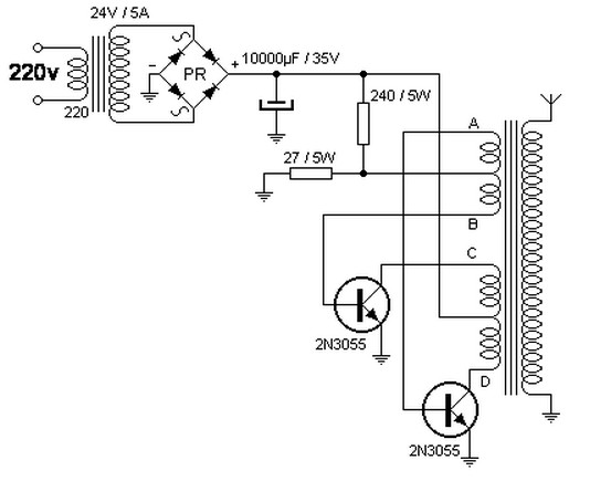
converter 220v ac to 40kv ac
The step-up transformer described can be repurposed as a flyback transformer from an unused television. It is advisable to utilize a basic model without a voltage tripler or high-voltage diode. This type of transformer is capable of generating voltages up...

measurement Measuring large differential voltage
A high voltage power supply is designed for an electron beam system. The voltage regulator utilizes an outdated analog system that operates through a comparator and a reference signal from a potentiometer (POT). The challenge involves the feedback voltage from...