


H-bridge using only n-channel mosfets
#H-bridge
#n-channel MOSFET
#floating gate drivers
#IGBTs
#schematic
#motor driver
#power electronics
#switching
#circuit design
#PCB

Description: An H-bridge circuit has been developed utilizing four floating gate drivers and four insulated gate bipolar transistors (IGBTs). The attached schematic illustrates one half of the H-bridge configuration. The circuit operates effectively, but there are additional considerations to address.
The H-bridge configuration is a crucial component in various applications, particularly in controlling the direction of a DC motor. The use of four floating gate drivers allows for efficient control of the IGBTs, which are known for their high efficiency and fast switching capabilities. Each IGBT is responsible for switching the current in the motor, enabling bidirectional control.
In the provided schematic, the floating gate drivers are connected to the gates of the IGBTs, ensuring that the transistors can be turned on and off with precision. The floating gate drivers are instrumental in providing the necessary voltage levels to fully enhance the IGBTs, thereby minimizing switching losses and improving overall performance.
The H-bridge operates by alternately switching pairs of IGBTs on and off. For instance, when the upper left and lower right IGBTs are activated, current flows in one direction, causing the motor to rotate in a specific direction. Conversely, activating the upper right and lower left IGBTs reverses the current flow, allowing for reverse rotation of the motor.
Design considerations for this H-bridge circuit include ensuring proper gate drive voltage levels, managing heat dissipation from the IGBTs, and implementing protection mechanisms such as overcurrent and overvoltage protection. Additionally, the layout of the PCB should minimize parasitic inductance and capacitance to enhance performance and reliability.
In summary, this H-bridge configuration, featuring floating gate drivers and IGBTs, is a robust solution for motor control applications, offering efficient operation and flexibility in direction control. Further refinements may enhance its performance and reliability in practical implementations.I have created an H-bridge PC with 4x floating gate drivers and 4x IGBTs (see attached schematic showing half of h-bridge). It works very nicely but I ..
The H-bridge configuration is a crucial component in various applications, particularly in controlling the direction of a DC motor. The use of four floating gate drivers allows for efficient control of the IGBTs, which are known for their high efficiency and fast switching capabilities. Each IGBT is responsible for switching the current in the motor, enabling bidirectional control.
In the provided schematic, the floating gate drivers are connected to the gates of the IGBTs, ensuring that the transistors can be turned on and off with precision. The floating gate drivers are instrumental in providing the necessary voltage levels to fully enhance the IGBTs, thereby minimizing switching losses and improving overall performance.
The H-bridge operates by alternately switching pairs of IGBTs on and off. For instance, when the upper left and lower right IGBTs are activated, current flows in one direction, causing the motor to rotate in a specific direction. Conversely, activating the upper right and lower left IGBTs reverses the current flow, allowing for reverse rotation of the motor.
Design considerations for this H-bridge circuit include ensuring proper gate drive voltage levels, managing heat dissipation from the IGBTs, and implementing protection mechanisms such as overcurrent and overvoltage protection. Additionally, the layout of the PCB should minimize parasitic inductance and capacitance to enhance performance and reliability.
In summary, this H-bridge configuration, featuring floating gate drivers and IGBTs, is a robust solution for motor control applications, offering efficient operation and flexibility in direction control. Further refinements may enhance its performance and reliability in practical implementations.I have created an H-bridge PC with 4x floating gate drivers and 4x IGBTs (see attached schematic showing half of h-bridge). It works very nicely but I ..

Using IRFP250 power tube H-bridge motor drive circuit
The drive circuit for the electromotor comprises a FET bridge circuit, a FET base drive circuit, a current sensor for the motor drive circuit, and a relay. The FET bridge circuit primarily consists of four high-power MOSFETs, which must possess...

H Bridge Direct Current Motor Control Circuits
This page features H-Bridge circuits used for controlling direct current motors. Several designs are shown using both CMOS and Bi-Polar power devices. These circuits could be used as the basis for Model Railroad DCC Boosters or PWM motor controllers. The...

How to Read a Schematic
Electronic circuits are presented in schematic form. A schematic is essentially a map that illustrates the path of current through various components. Each component is represented by a symbol, typically accompanied by a label or a value, or both. The...

6 Transistor Tildens H-Bridge
This diagram illustrates the 6-transistor Tilden H-bridge circuit. While it is not as old as the original basic H-bridge, it has a significant history and serves as the foundation for many BEAM driver circuits. Revised drawings were created for Ian...

High-performance power supply LM334
The circuit functions as a switching power supply designed to operate alongside a linear regulated power supply. Key characteristics include high efficiency and low dropout voltage. It effectively filters out high-frequency ripple voltage and manages instantaneous voltage variations, making it...

h bridge driver circuit
The regenerative effect of a 4-quadrant inverter necessitates power dissipation in some form. In large industrial drives, this power is typically re-inverted back onto the national grid. However, for smaller applications, implementing a braking circuit is advisable. For low-power applications...
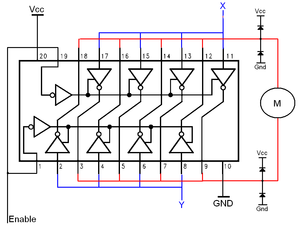
Simple H-bridges Tutorial
The H-bridge is a well-known and widely used circuit configuration for driving brushed DC motors. It enables straightforward control of motor direction, allowing for both forward and reverse operation.
The H-bridge circuit consists of four switches, typically implemented using transistors or...
printed circuit board pcb etching
This text assumes some prior knowledge of PCB etching methods and recounts an experience with the toner transfer technique. For those unfamiliar with the method, additional research may be necessary. The process of constructing a circuit on protoboard is relatively...

Driving a Capacitive Load with an H-bridge
Following the publication of a previous post, some unusual issues were encountered, which required several days to clarify. The main focus was on building a simple Class D amplifier designed to provide an EL panel with a +/- 120V square...