


L293 Basic Bipolar Stepper Motor Driver Configuration Circuit
#L293
#L298N
#bipolar stepper motor
#motor driver
#two phase
#stepper motor control
#H-bridge
#driver configuration

Description: This circuit illustrates a basic configuration for driving a bipolar stepper motor using either an L293 or an L298N driver. It demonstrates that a single device can control a two-phase bipolar stepper motor.
The circuit employs either the L293 or L298N integrated circuit, both of which are designed for driving motors and can handle bi-directional control of the stepper motor phases. The bipolar stepper motor consists of two coils that need to be energized in a specific sequence to achieve rotation. The L293 and L298N drivers facilitate this by providing the necessary current and voltage levels to the motor coils.
In this configuration, the control signals are typically generated by a microcontroller, which sends pulse-width modulation (PWM) signals to the driver IC. The driver IC interprets these signals and activates the appropriate outputs to energize the motor coils in the correct order. This is crucial for creating the magnetic fields that cause the motor to step forward or backward.
The L293 driver can handle up to 600 mA per channel, making it suitable for smaller stepper motors, while the L298N can handle up to 2 A per channel, allowing it to drive larger motors. Both devices include built-in diodes for flyback protection, which is essential for preventing voltage spikes generated by the inductive loads of the motor coils from damaging the driver circuitry.
For optimal performance, it is important to ensure that the power supply voltage is within the specifications of the chosen driver and motor. Additionally, proper heat dissipation measures should be implemented, especially when using the L298N, as it can generate significant heat during operation.
Overall, this circuit configuration provides a straightforward and effective means of controlling a bipolar stepper motor, suitable for various applications in robotics, automation, and other fields requiring precise motor control.The herein circuit shows basic configuration for bipolar stepper motor driving which can be applied using either an L293 or an L298N. This circuit shows that a single device can be used to drive a two phase bipolar stepper motor
The circuit employs either the L293 or L298N integrated circuit, both of which are designed for driving motors and can handle bi-directional control of the stepper motor phases. The bipolar stepper motor consists of two coils that need to be energized in a specific sequence to achieve rotation. The L293 and L298N drivers facilitate this by providing the necessary current and voltage levels to the motor coils.
In this configuration, the control signals are typically generated by a microcontroller, which sends pulse-width modulation (PWM) signals to the driver IC. The driver IC interprets these signals and activates the appropriate outputs to energize the motor coils in the correct order. This is crucial for creating the magnetic fields that cause the motor to step forward or backward.
The L293 driver can handle up to 600 mA per channel, making it suitable for smaller stepper motors, while the L298N can handle up to 2 A per channel, allowing it to drive larger motors. Both devices include built-in diodes for flyback protection, which is essential for preventing voltage spikes generated by the inductive loads of the motor coils from damaging the driver circuitry.
For optimal performance, it is important to ensure that the power supply voltage is within the specifications of the chosen driver and motor. Additionally, proper heat dissipation measures should be implemented, especially when using the L298N, as it can generate significant heat during operation.
Overall, this circuit configuration provides a straightforward and effective means of controlling a bipolar stepper motor, suitable for various applications in robotics, automation, and other fields requiring precise motor control.The herein circuit shows basic configuration for bipolar stepper motor driving which can be applied using either an L293 or an L298N. This circuit shows that a single device can be used to drive a two phase bipolar stepper motor

sn754410
After testing the motors, a current draw of up to 1.3 Amps was observed. Two SN754410 H-Bridges were stacked, and a heat sink was constructed from an aluminum can. This setup should handle 2 Amps or more. The heat sink...
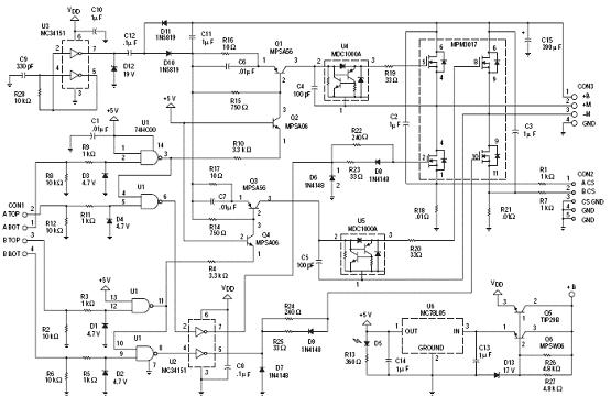
N-Channel H-bridge Motor Drive
The following circuit illustrates an N-Channel H-bridge motor drive circuit diagram. Features include low voltage motor drives utilizing N-channel MOSFETs.
The N-Channel H-bridge motor drive circuit is designed to control the direction and speed of a DC motor using low voltage....

6-transistor H-bridge
Mark Tilden's 6-transistor H-bridge Design, limitations, usage
This is the six transistor "Tilden style" H-bridge; while not as old as the original "basic H-bridge," this goes "way back," and is the basis for many BEAM driver circuits.
* Up to 800 mA...

10A H-Bridge Motor Controller Circuit
The 10A H-Bridge Motor Controller circuit appears straightforward, but several critical aspects should not be overlooked. The primary components utilized in the circuit include the TIP147, TIP142, and 2N2222 transistors. The power supply circuit operates at +12V, which is fed...

Music Driven Motor Schematic
Music Driven Motor Schematic. The geared motor drives the stem of a dancing flower to the beat of music.
The music-driven motor schematic involves a geared motor that is activated in response to sound signals, specifically music. This design typically incorporates...

how to design h bridge circuit for
In electronics, an H-bridge circuit refers to a configuration consisting of four individual switching devices, such as transistors or MOSFETs, which can be controlled by external discrete signals from the respective stages of the control circuit. During operation, the complementary...
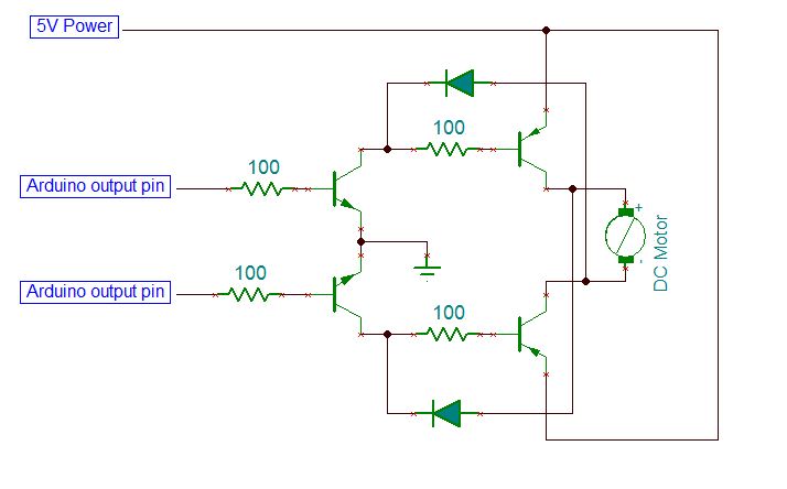
STHS Computer Technology
On the breadboard, construct two bi-directional motor control circuits, commonly referred to as "H-bridge" circuits. These circuits will manage the two DC motors that propel the wheels. Each circuit will have two wires connected to the Arduino (one for forward...

5A H-Bridge Module Pinout Circuit Schematic for Bipolar DC Motor
The schematic presented illustrates a 5A H-Bridge Module designed for the operation of a single Bipolar DC motor. The H-Bridge Module includes a header set (J2) and a connector terminal set (J1). Below is the pinout description for the J2...

L298N Stepper Motor Driver Controller Board for Arduino
The L298N driver module incorporates the ST L298N chip, commonly utilized to drive two DC motors with voltage ratings between 3V and 30V. It features a 5V output interface that provides power for 5V single-chip circuitry and supports 3.3V MCU...