


L293 reversible motor drive circuit diagram
#L293
#motor driver
#TTL compatible
#Darlington transistor
#totem pole
#reversible motor
#H-bridge
#driver enable

Description: All inputs are compatible with TTL. Each output consists of a complete totem pole driver circuit, utilizing Darlington transistors and pseudo-Darlington sources. The driver enable signals, labeled as 1,2 EN and 3,4 EN, control the activation of drivers 1 and 2, as well as drivers 3 and 4. When the enable input is high, the corresponding driver is activated, resulting in an active output in the input stage. Conversely, when the enable input is low, the drivers are disabled, placing the output in a high impedance state. With appropriate data input, each driver can form a complete H-bridge for reversible motor or solenoid applications. The high current L293 quadruple half-bridge integrated circuit is designed for simple, high-efficiency motor control. The L293 can provide a bidirectional drive current of 1 A with a voltage range of 4V to 36V, while the L293D supports a bidirectional drive current of 600 mA within the same voltage range. Both devices are suitable for driving inductive loads such as relays, solenoids, DC motors, and bipolar stepper motors, as well as other high-current applications that require positive supply voltages.
The described circuit employs TTL-compatible inputs and outputs, ensuring seamless integration with various digital logic systems. The totem pole configuration allows for efficient driving of loads, maximizing current delivery while maintaining low output impedance when active. The use of Darlington transistors enhances the current gain, enabling the circuit to control larger loads without excessive input current.
The enable signals (1,2 EN and 3,4 EN) play a critical role in managing the operation of the drivers. By applying a high signal to these inputs, the corresponding drivers are activated, allowing current to flow through the outputs. This feature is essential for applications requiring precise control over motor direction and operation, as it enables users to switch between forward and reverse motion by appropriately toggling the enable signals.
The L293 and L293D integrated circuits are specifically designed to handle inductive loads, which are common in motor control applications. The L293 can handle a continuous current of 1 A per channel, making it suitable for larger motors or multiple smaller motors. The L293D, with its lower current rating of 600 mA, is ideal for smaller applications or where space is a constraint. Both chips include built-in diodes for flyback protection, which safeguard the circuit from voltage spikes generated when inductive loads are switched off.
This configuration allows for the implementation of H-bridge circuits, which can control the direction of a motor by reversing the polarity of the voltage applied to its terminals. This capability is essential for applications such as robotics, where precise control over movement is required. The ability to place the outputs in a high impedance state when the drivers are disabled further enhances the versatility of the circuit, allowing for safe and efficient operation without risking damage to the components.
In summary, the combination of TTL compatibility, totem pole driver circuits, and the use of L293 and L293D integrated circuits provides a robust solution for controlling motors and solenoids in a variety of electronic applications. The detailed operation of the enable signals and the characteristics of the driver outputs ensure that this circuit can effectively manage the demands of high-current applications while maintaining reliability and efficiency.All input is compatible with TTL. Each output is a complete totem pole driver circuit, Darlington transistors chip and pseudo-Darling source. Driver enable, 1,2 EN and drivers 3 and 4 by a 3,4 EN Enable Enable drives 1 and 2. When the enable input is high, the associated driver is enabled, the output active in the input stage with them. When the enable input is low, these drivers are disabled, and the output is closed, in a high impedance state.
With the right data entry, each driver to form a complete H (or bridge) for reversible drive motor or solenoid applications. High current L293 quadruple half - driving integrated circuit H, we can design a very simple high-efficiency motor control L293 is designed to provide a voltage bidirectional drive current of 1 A 4.V to 3V is designed to provide the L293D bidirectional drive current 600 mA voltage from 4.V to 36 V.
both devices are designed to drive inductive loads, such as relays, solenoids, DC and bipolar stepper motors, and other high-current/high positive supply load voltage applications. All input is compatible with TTL. Each output is a complete totem pole driver circuit, Darlington transistors chip and pseudo-Darling source.
Driver enable, 1,2 EN and drivers 3 and 4 by a 3,4 EN Enable Enable drives 1 and 2. When the enable input is high, the associated driver is enabled, the output active in the input stage with them. When the enable input is low, these drivers are disabled, and the output is closed, in a high impedance state.
With the right data entry, each driver to form a complete H (or bridge) for reversible drive motor or solenoid applications.
The described circuit employs TTL-compatible inputs and outputs, ensuring seamless integration with various digital logic systems. The totem pole configuration allows for efficient driving of loads, maximizing current delivery while maintaining low output impedance when active. The use of Darlington transistors enhances the current gain, enabling the circuit to control larger loads without excessive input current.
The enable signals (1,2 EN and 3,4 EN) play a critical role in managing the operation of the drivers. By applying a high signal to these inputs, the corresponding drivers are activated, allowing current to flow through the outputs. This feature is essential for applications requiring precise control over motor direction and operation, as it enables users to switch between forward and reverse motion by appropriately toggling the enable signals.
The L293 and L293D integrated circuits are specifically designed to handle inductive loads, which are common in motor control applications. The L293 can handle a continuous current of 1 A per channel, making it suitable for larger motors or multiple smaller motors. The L293D, with its lower current rating of 600 mA, is ideal for smaller applications or where space is a constraint. Both chips include built-in diodes for flyback protection, which safeguard the circuit from voltage spikes generated when inductive loads are switched off.
This configuration allows for the implementation of H-bridge circuits, which can control the direction of a motor by reversing the polarity of the voltage applied to its terminals. This capability is essential for applications such as robotics, where precise control over movement is required. The ability to place the outputs in a high impedance state when the drivers are disabled further enhances the versatility of the circuit, allowing for safe and efficient operation without risking damage to the components.
In summary, the combination of TTL compatibility, totem pole driver circuits, and the use of L293 and L293D integrated circuits provides a robust solution for controlling motors and solenoids in a variety of electronic applications. The detailed operation of the enable signals and the characteristics of the driver outputs ensure that this circuit can effectively manage the demands of high-current applications while maintaining reliability and efficiency.All input is compatible with TTL. Each output is a complete totem pole driver circuit, Darlington transistors chip and pseudo-Darling source. Driver enable, 1,2 EN and drivers 3 and 4 by a 3,4 EN Enable Enable drives 1 and 2. When the enable input is high, the associated driver is enabled, the output active in the input stage with them. When the enable input is low, these drivers are disabled, and the output is closed, in a high impedance state.
With the right data entry, each driver to form a complete H (or bridge) for reversible drive motor or solenoid applications. High current L293 quadruple half - driving integrated circuit H, we can design a very simple high-efficiency motor control L293 is designed to provide a voltage bidirectional drive current of 1 A 4.V to 3V is designed to provide the L293D bidirectional drive current 600 mA voltage from 4.V to 36 V.
both devices are designed to drive inductive loads, such as relays, solenoids, DC and bipolar stepper motors, and other high-current/high positive supply load voltage applications. All input is compatible with TTL. Each output is a complete totem pole driver circuit, Darlington transistors chip and pseudo-Darling source.
Driver enable, 1,2 EN and drivers 3 and 4 by a 3,4 EN Enable Enable drives 1 and 2. When the enable input is high, the associated driver is enabled, the output active in the input stage with them. When the enable input is low, these drivers are disabled, and the output is closed, in a high impedance state.
With the right data entry, each driver to form a complete H (or bridge) for reversible drive motor or solenoid applications.

Wilf Rigter`s reversing H-bridge
This H-bridge variant was one of the first in which the reversing circuitry is built into the driver, rather than (as is more-commonly done) into the control circuitry upstream of the driver. This is a handy circuit, though, for 2-motor...
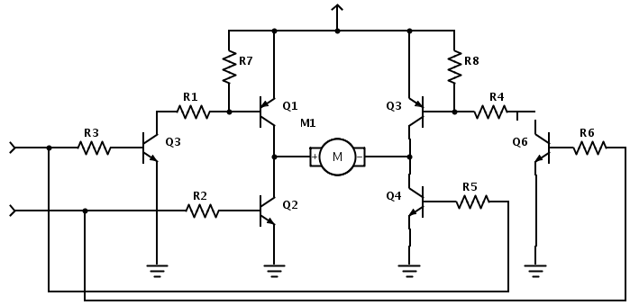
how H-brigde is working
Please help me understand how this H-bridge works. I have tried, but I couldn't make any sense of it. I know the general functioning of the circuit, but I don't fully grasp the details.
An H-bridge is a specific type of...
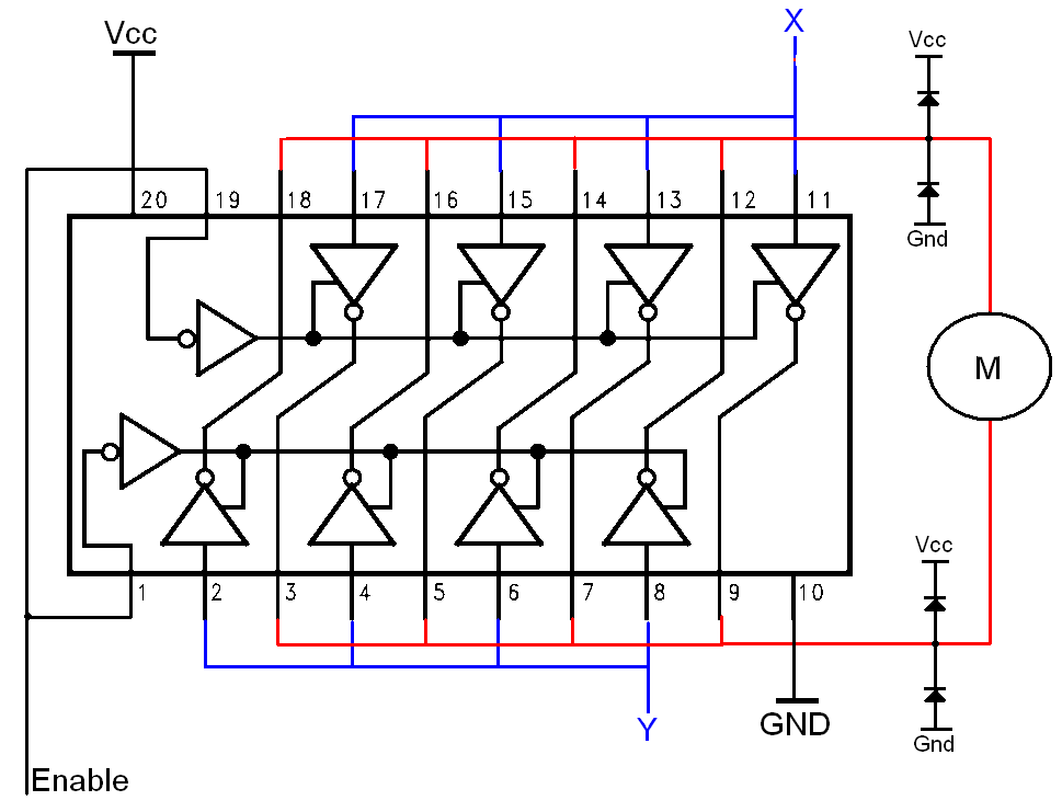
Simple H-bridges Tutorial
The H-bridge is a well-known and widely used circuit configuration for driving brushed DC motors. It enables straightforward control of motor direction, allowing for both forward and reverse operation.
The H-bridge circuit consists of four switches, typically implemented using transistors or...
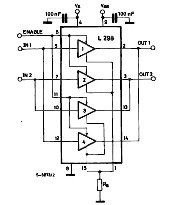
dc motor driver with h bridge ic l293d
The L298 IC H-Bridge DC motor driver features two H-Bridge circuits, allowing it to control two DC motors simultaneously. Each H-Bridge can deliver currents up to 2A, but when used in parallel, the L298 can provide a total current of...

6-transistor H-bridge
Mark Tilden's 6-transistor H-bridge Design, limitations, usage
This is the six transistor "Tilden style" H-bridge; while not as old as the original "basic H-bridge," this goes "way back," and is the basis for many BEAM driver circuits.
* Up to 800 mA...

Another simple H-Bridge circuit
You have 4 transistors, wired as ON OFF switches. Two signal lines allow you to run the motor in one direction, when reversed, the motor runs in the other direction. It's very straightforward to use and build, but be careful...

motor driver circuit
These circuits are commonly utilized in robotics to enable DC motors to operate in both forward and reverse directions, as well as to provide an electric brake (short circuit condition). H-bridges can be found as integrated circuits or can be...

transistors Can someone help me understand this H-Bridge
An old RC car is available, but it lacks the transmitter. A custom receiver/transmitter has been built using a microcontroller and a 2.4 GHz transceiver. However, there is uncertainty regarding the functionality of the car's original H-Bridge circuit.
The H-Bridge is...
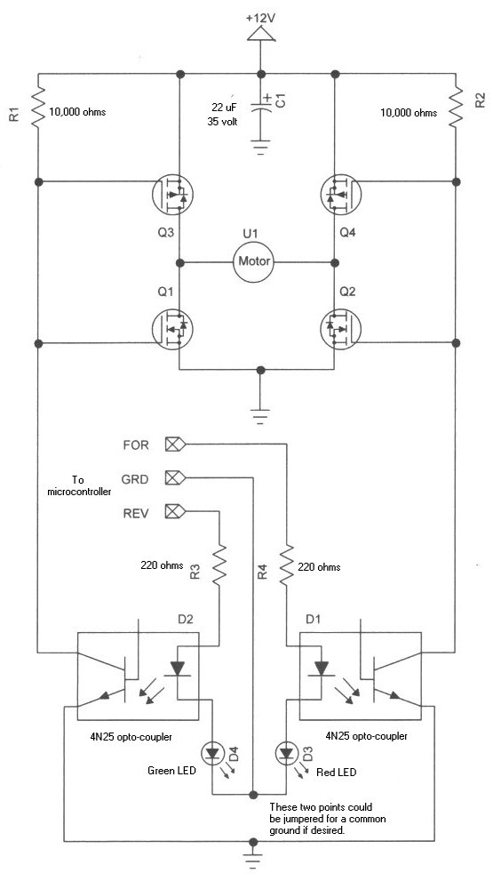
h bridge
Learning how to use power MOSFETs by building an H-bridge motor control.
The H-bridge motor control circuit is an essential configuration for driving DC motors in both forward and reverse directions. It utilizes four power MOSFETs arranged in a bridge configuration,...