


motion motor control servo system block
#servo system
#closed-loop feedback
#motor driver
#speed control
#position control
#automated systems
#feedback elements
#motion control

Description: This figure illustrates a block diagram of modern automated systems that incorporate closed-loop feedback for motion control. These systems typically feature a servo system consisting of feedback elements and a motor driver, which work together to provide accurate and stable control over speed and position. The diagram below depicts the various components of a typical servo system. For processing high-speed encoder signals, standard motion-controller cards and modules include a motion-control integrated circuit (IC), a microprocessor, and a digital signal processor (DSP) or custom application-specific integrated circuit (ASIC). The controller generates velocity and direction of rotation signals for the driver or amplifier, which in turn supplies the appropriate levels of voltage and current (power) necessary to operate the motor. Key considerations for designing a robust and fault-tolerant motion-control system with feedback include the controller-encoder input circuits (receiver circuits), the layout of the receiver circuit PC board, and the encoder-signal cabling system. Additionally, motion-controller inputs, such as hard-wired emergency stop and limit inputs, should be taken into account when designing a fault-tolerant feedback system, although these aspects are not covered in this article.
The block diagram presented illustrates the architecture of a modern automated motion control system, emphasizing the integration of closed-loop feedback mechanisms. At its core, the servo system consists of critical components such as feedback sensors, motor drivers, and control circuitry, which collectively ensure precise regulation of motor speed and positioning.
The feedback elements, typically comprising encoders, provide real-time data regarding the motor's position and speed. This information is relayed to the motion controller, which processes the signals using a motion-control IC, microprocessor, or DSP. These processing units are essential for interpreting the encoder signals and for generating the necessary control outputs to the motor driver.
The motor driver, which may consist of an amplifier, receives commands from the motion controller. It is responsible for delivering the correct voltage and current levels to the motor, thereby facilitating accurate motion execution. The integration of these components allows for dynamic adjustments based on feedback, ensuring that the system can maintain stability and precision even under varying operational conditions.
In designing a fault-tolerant motion-control system, several critical factors must be addressed. The layout of the receiver circuit's PC board must be optimized to minimize noise and interference, which can adversely affect performance. Moreover, the cabling system for encoder signals should be robust and shielded to prevent signal degradation.
It is also important to incorporate safety features such as hard-wired emergency stop and limit inputs into the motion controller. These features enhance the reliability of the system by providing immediate shutdown capabilities in case of faults or emergencies. Overall, a well-designed motion-control system integrates these elements cohesively, ensuring operational reliability and safety while achieving the desired motion performance.This is a figure for a block diagram of a modern automated systems incorporate closed-loop feedback for motion control. They typically include a servo system that consist of feedback elements and motor driver combined in a manner.
This will give accurate and stable control over speed and position. Below is the illustration of the various system-le vel components of a typical servo system. This is the figure of the diagram; For processing the high-speed encoder signals, typical motion-controller cards and modules include a motion-control IC, a microprocessor, and a DSP or custom ASIC. Velocity and direction of rotation signals to the driver or amplifier is provided by the controller which in turn provides the proper levels of voltage and current (power) to operate the motor.
We must have address the following items at the system level to design robust and fault-tolerant motion-control system with feedback during design: Controller-encoder input circuits (receiver circuits), Receiver circuit PC-board layout and Encoder-signal cabling system. Motion-controller inputs, such as hard-wired emergency stop and limit inputs, should also be considered when designing a fault-tolerant feedback system though not addressed in this article.
The block diagram presented illustrates the architecture of a modern automated motion control system, emphasizing the integration of closed-loop feedback mechanisms. At its core, the servo system consists of critical components such as feedback sensors, motor drivers, and control circuitry, which collectively ensure precise regulation of motor speed and positioning.
The feedback elements, typically comprising encoders, provide real-time data regarding the motor's position and speed. This information is relayed to the motion controller, which processes the signals using a motion-control IC, microprocessor, or DSP. These processing units are essential for interpreting the encoder signals and for generating the necessary control outputs to the motor driver.
The motor driver, which may consist of an amplifier, receives commands from the motion controller. It is responsible for delivering the correct voltage and current levels to the motor, thereby facilitating accurate motion execution. The integration of these components allows for dynamic adjustments based on feedback, ensuring that the system can maintain stability and precision even under varying operational conditions.
In designing a fault-tolerant motion-control system, several critical factors must be addressed. The layout of the receiver circuit's PC board must be optimized to minimize noise and interference, which can adversely affect performance. Moreover, the cabling system for encoder signals should be robust and shielded to prevent signal degradation.
It is also important to incorporate safety features such as hard-wired emergency stop and limit inputs into the motion controller. These features enhance the reliability of the system by providing immediate shutdown capabilities in case of faults or emergencies. Overall, a well-designed motion-control system integrates these elements cohesively, ensuring operational reliability and safety while achieving the desired motion performance.This is a figure for a block diagram of a modern automated systems incorporate closed-loop feedback for motion control. They typically include a servo system that consist of feedback elements and motor driver combined in a manner.
This will give accurate and stable control over speed and position. Below is the illustration of the various system-le vel components of a typical servo system. This is the figure of the diagram; For processing the high-speed encoder signals, typical motion-controller cards and modules include a motion-control IC, a microprocessor, and a DSP or custom ASIC. Velocity and direction of rotation signals to the driver or amplifier is provided by the controller which in turn provides the proper levels of voltage and current (power) to operate the motor.
We must have address the following items at the system level to design robust and fault-tolerant motion-control system with feedback during design: Controller-encoder input circuits (receiver circuits), Receiver circuit PC-board layout and Encoder-signal cabling system. Motion-controller inputs, such as hard-wired emergency stop and limit inputs, should also be considered when designing a fault-tolerant feedback system though not addressed in this article.

Big Trak Motor Driver Schematic
Schematic of Big Trak's motor driver circuit. The toy includes 9112 and 9113 transistors (and sometimes 2N6715) because the 75494 chip cannot supply enough current to run the Big Trak's motors by itself.
The motor driver circuit for the Big Trak...

Forward and reverse speed control circuit can be integrated with a brake function
Figure 3173 illustrates a control circuit for a wound rotor induction motor that enables mechanical braking, dynamic braking, and reverse braking functions. The circuit includes various components such as relays, contactors, and time relays to manage the motor's speed in...

Mixer or Sewing Machine Motor Speed Control
A simple half-wave motor speed control circuit is effective for small universal AC/DC motors, with a maximum current capability of two amps RMS.
The half-wave motor speed control circuit utilizes a diode to allow current to flow in only one direction,...

Two motor speed control circuit and the main level indicating circuit
The circuit illustrated in Figure 3-178 is designed for controlling the speed and torque of a motor used in a continuous casting machine. It consists of the main circuit, a trigger circuit, and both manual and automatic control signal circuits,...

Motion (Motor) Control Servo System Block Diagram
Below is a block diagram of modern automated systems that incorporate closed-loop feedback for motion control. They typically include a servo system that consists of various components.
Automated systems utilizing closed-loop feedback mechanisms are designed to enhance precision and responsiveness in...
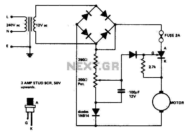
Speed control for model trains or cars
Low voltage speed control provides excellent starting torque and effective speed regulation. Additionally, a reversing switch can be integrated into the motor leads.
Low voltage speed control circuits are essential in applications where precise motor control is required, such as in...
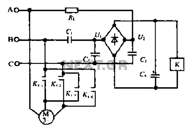
A motor reversing automatic adjustment circuit
Composition ratio circuit. The circuit consists of resistors and capacitors that form a shift register circuit with diodes VD1 to VD4, creating a bridge for electric current. Capacitor C4 is utilized for filtering applications and for eliminating instantaneous relay energization...
Big Trak Motor Driver Schematic
Schematic of Big Trak's motor driver circuit. The toy includes 9112 and 9113 transistors (and sometimes 2N6715) because the 75494 chip cannot supply enough current to run the Big Trak's motors by itself.
The motor driver circuit for the Big Trak...

Multi-unit slip motor speed control system synchronous operation circuit
Collaboration with the dancers balanced bridge long on the porcelain unit. A sync adjustment rheostat speed control system is shown in Figure 3. The principle of speed control for electro-magnetic and photoelectric dancers is similar. The main motor (BQ2) allows...