


Multiple Servomotors
#servomotors
#pulse width modulation
#I/O control
#microcontroller
#PWM
#robotics
#automation
#precision control
#embedded systems

Description: A modified version of the previous program allows control of multiple servomotors, utilizing all available I/O lines on port B. The following listing demonstrates the control of two servos similarly to how a single servo was managed in the earlier program. The associated circuit is depicted in figure 4 below. The program employs two pulse width variables, pw1 and pw2, along with two sets of routines: left1 and left2, right1 and right2, corresponding to each motor. In the schematic, the first servo is connected as in the earlier circuit, while the second servo utilizes B3 for its pulse output, and B4 and B5 are designated for the SPDT switch.
The circuit design facilitates control of two servomotors through a microcontroller's port B, leveraging its I/O capabilities. Each servo is driven by a pulse width modulation (PWM) signal, which is generated using the defined pulse width variables pw1 and pw2. These variables determine the duration of the high signal in the PWM cycle, effectively controlling the position of the servos.
The first servo is connected in accordance with the configuration from the previous program, ensuring a familiar setup for users. The second servo, however, introduces additional complexity by utilizing pin B3 for its PWM signal. Pins B4 and B5 are employed for an SPDT (Single Pole Double Throw) switch, which allows for alternate control modes or functionality. This arrangement can facilitate features such as switching between different servo positions or modes of operation, enhancing the versatility of the circuit.
The routines left1, left2, right1, and right2 are specifically programmed to manage the movement of the respective servos, allowing for coordinated control based on user input or pre-defined sequences. The overall design emphasizes modularity and scalability, enabling users to expand the system further by adding more servos if additional I/O lines are available. The use of pulse width modulation is critical in ensuring smooth and precise control of the servos, making this circuit suitable for applications requiring accurate positioning, such as robotics or automated systems.Using a modified version of the last program, we can control as many servomotors as we have I/O lines on port B. In the next listing, we will control two servos in the same manner as we controlled a single servo in the previous program.
The circuit is shown in figure 4 (below). The program uses two pulsewidth variables, pw1 and pw2; and two sets o f routines, left1 and left2, right1 and right2; one for each motor. As you can see in the schematic, the first servo is wired as per the previous circuit. The second servo is now using B3 as it`s pulse out, and B4 and B5 for the SPDT switch.
The circuit design facilitates control of two servomotors through a microcontroller's port B, leveraging its I/O capabilities. Each servo is driven by a pulse width modulation (PWM) signal, which is generated using the defined pulse width variables pw1 and pw2. These variables determine the duration of the high signal in the PWM cycle, effectively controlling the position of the servos.
The first servo is connected in accordance with the configuration from the previous program, ensuring a familiar setup for users. The second servo, however, introduces additional complexity by utilizing pin B3 for its PWM signal. Pins B4 and B5 are employed for an SPDT (Single Pole Double Throw) switch, which allows for alternate control modes or functionality. This arrangement can facilitate features such as switching between different servo positions or modes of operation, enhancing the versatility of the circuit.
The routines left1, left2, right1, and right2 are specifically programmed to manage the movement of the respective servos, allowing for coordinated control based on user input or pre-defined sequences. The overall design emphasizes modularity and scalability, enabling users to expand the system further by adding more servos if additional I/O lines are available. The use of pulse width modulation is critical in ensuring smooth and precise control of the servos, making this circuit suitable for applications requiring accurate positioning, such as robotics or automated systems.Using a modified version of the last program, we can control as many servomotors as we have I/O lines on port B. In the next listing, we will control two servos in the same manner as we controlled a single servo in the previous program.
The circuit is shown in figure 4 (below). The program uses two pulsewidth variables, pw1 and pw2; and two sets o f routines, left1 and left2, right1 and right2; one for each motor. As you can see in the schematic, the first servo is wired as per the previous circuit. The second servo is now using B3 as it`s pulse out, and B4 and B5 for the SPDT switch.

PWM Motor Speed Controller / DC Light Dimmer
A pulse width modulator (PWM) is a device that can be utilized as an efficient light dimmer or DC motor speed controller. The circuit described here is intended for general-purpose applications, capable of controlling DC devices that draw up to...
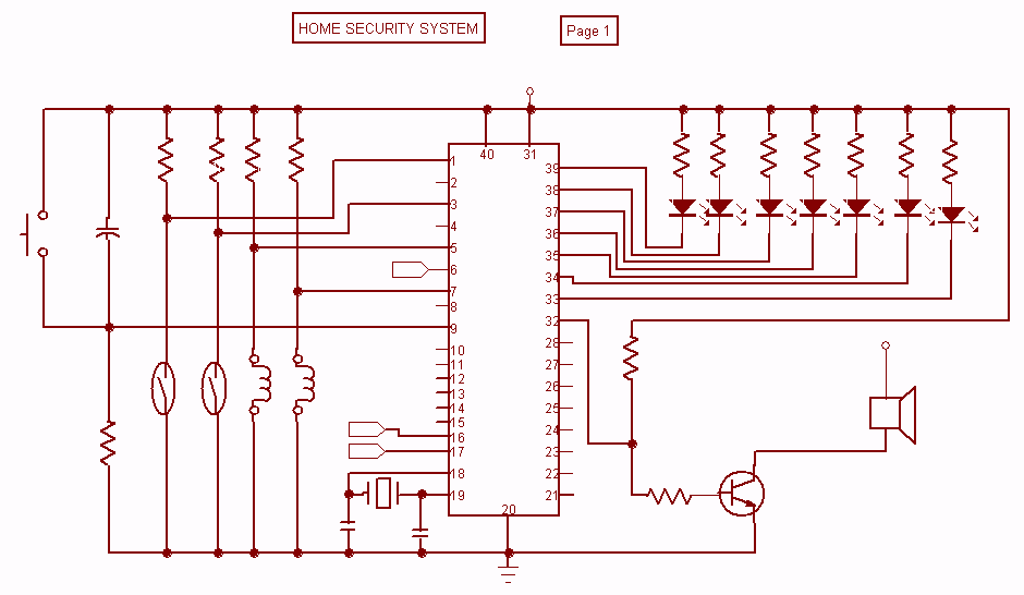
Home Security System with microcontroller
Security is a prime concern in our day-to-day life. Everyone wants to be as much secure as possible. An access control for doors forms a vital link in a security chain. The Microcontroller based Home Security System can be adopted...

8 Channel software controlled fanbus with PWM
This article was previously published, but the intention is to spread the idea further, potentially inspiring new concepts. An improved version was being developed using an ULN2803A instead of multiple BC547B transistors and optional Zener diodes to ensure that the...

Simple DC motor PWM speed control
The 555 IC is configured as an astable multivibrator, producing a constant frequency independent of the duty cycle. The total resistance (R_charge + R_discharge, with the diode in consideration) remains constant at 22 kΩ, resulting in a frequency of approximately...
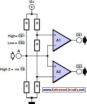
Multitasking Pins circuit
It is entirely logical that low-cost miniature microcontrollers have fewer pins than their larger counterparts, sometimes too few. Consideration has been given to how to economize on pins by making them perform the work of several. It was noted that...

µP-Controlled Oscillator Delivers Rock-Bottom Distortion
Function generators are essential in the design, testing, and operation of encoders, modulators, demodulators, and measurement instruments. This document presents an economical method to construct a bus-controlled sinewave oscillator that exhibits exceptionally low distortion. The circuit produces a sinusoidal output...

AirBorn Electronics project
Embedded system design engineers create examples of their work from the 1990s era.
Embedded systems have evolved significantly since the 1990s, and the design work from that period reflects the technological limitations and innovations of the time. Engineers in this field...

Pulse-Width-Modulated Motor-Speed Control Circuit
Connected in this manner, an LM317 1-A adjustable-voltage regulator can be utilized to control the speed of a miniature DC motor or to adjust the brightness of a small lamp. The circuit achieves this by modulating the pulse width, and...

DC Motor Speed Controller
This article demonstrates how to control a DC motor using an H-bridge driver chip with PWM output from a PIC microcontroller for speed control. While a PIC microcontroller is utilized, other controllers such as AVRs, Basic Stamps, and certain Picaxe...