


PC Fan Controller Circuit
#PC fan
#12V
#temperature sensor
#KTY10
#voltage control
#discrete components
#current limit
#cooling
#thermal management

Description: This PC fan controller circuit is designed with discrete components to control 12V fans that consume less than 200mA. The specified component values in the circuit diagram ensure that the voltage will not drop below 7V. If the fan fails to start at 25°C, temporarily replace the temperature sensor KTY10 with a 1.8kΩ resistor and reduce the value of R7. If the PC fan operates at excessive speed, the value of R7 should be increased. Transistors T1 and T2 compare the fixed potential from the common point of resistors R3 and R4 with the temperature-dependent potential from the common point of resistors R1 and R2. It may be beneficial to connect a 25kΩ potentiometer in place of R2 for fine-tuning until the fan operates at the desired speed, after which the potentiometer can be measured and replaced with a fixed resistor of the same value. The temperature sensor should be positioned in the warm air stream of the fan. Upon connecting the PC, the fan's rotational speed will initially be high due to capacitor C1 but will decrease to a minimum value. The air temperature near the sensor should be measured with a thermometer. The controller circuit will activate when the temperature reaches 35°C. If this does not occur, the value of R2 should be modified or the potentiometer replaced in its place should be adjusted. As the temperature rises, the fan's rotational speed will increase, although the maximum speed will be lower than that achieved without the control circuit.
This PC fan controller circuit utilizes a combination of discrete components to effectively manage the operation of 12V DC fans, particularly those with a current draw not exceeding 200mA. The circuit ensures stable operation by preventing the voltage from dropping below 7V, which is crucial for maintaining fan performance.
The core of the circuit is built around two transistors, T1 and T2, which function as a comparator. These transistors compare the fixed voltage derived from resistors R3 and R4 against a temperature-dependent voltage generated by resistors R1 and R2. This configuration allows for precise control over the fan speed based on the ambient temperature, as sensed by the KTY10 temperature sensor.
In scenarios where the fan does not start at lower temperatures (e.g., 25°C), a temporary workaround involves replacing the temperature sensor with a fixed resistor (1.8kΩ) to bypass the temperature dependency. Additionally, adjustments to resistor R7 can calibrate the fan's operational speed; increasing R7 will reduce the fan speed, while decreasing it will allow for higher speeds.
For further fine-tuning, it is advisable to incorporate a 25kΩ potentiometer in place of R2. This allows for real-time adjustments to the temperature threshold at which the fan begins to operate. Once the desired setting is achieved, the potentiometer's resistance can be measured and replaced with a fixed resistor of equivalent value, ensuring stability in operation.
The placement of the temperature sensor is critical; it should be positioned in the warm air stream of the fan to accurately gauge the temperature. Initially, when the PC is powered on, the fan may operate at a high speed due to the charging of capacitor C1. However, as the system stabilizes, the fan speed will decrease to a minimum operational level.
The controller is designed to activate at a threshold temperature of 35°C. If the fan does not respond as expected, adjustments to R2 or the potentiometer can be made to modify the activation point. As the temperature rises, the fan speed will correspondingly increase, though it is important to note that the maximum speed will be inherently limited compared to a configuration without the control circuit. This design not only enhances the efficiency of the cooling system but also contributes to reduced noise levels and improved thermal management within the PC environment.This PC fan controller circuit is designed with discrete components and is used to control 12 V fans that have a current consumption lower than 200mA. With the components values presented in the circuit diagram, the voltage won`t drop below 7V. If the fan won`t start at 25 °C then temporarily replace the temperature sensor KTY10 with a 1. 8k © resi stor and reduce the value of R7. If the PC fan has a speed too high then increase the R7 value. T1 and T2 transistors compare the fixed potentional from R3-R4 common point with the temperature dependent potentional of R1-R2 common point. It may be useful to connect a 25k © potentiometer instead of R2 and to adjust it until the PC fan is at the correct speed and to measure its resistance and then replace it with a fix resistor with the same value.
Place the temperature sensor in the warm air of the fan. When the PC is connected the speed rotation of the fan will be pretty high because of C1 but will decrease at a minimum value. Measure with a thermometer the air temperature close to the sensor. When the temperature reaches 35 °C the controller circuit will start to work. If this won`t happen modify the value of R2 or adjust a potentiometer placed instead of R2. When the temperature increases so will the rotation speed of the PC fan. The maximum speed will be lower than the one obtained without the control circuit.
This PC fan controller circuit utilizes a combination of discrete components to effectively manage the operation of 12V DC fans, particularly those with a current draw not exceeding 200mA. The circuit ensures stable operation by preventing the voltage from dropping below 7V, which is crucial for maintaining fan performance.
The core of the circuit is built around two transistors, T1 and T2, which function as a comparator. These transistors compare the fixed voltage derived from resistors R3 and R4 against a temperature-dependent voltage generated by resistors R1 and R2. This configuration allows for precise control over the fan speed based on the ambient temperature, as sensed by the KTY10 temperature sensor.
In scenarios where the fan does not start at lower temperatures (e.g., 25°C), a temporary workaround involves replacing the temperature sensor with a fixed resistor (1.8kΩ) to bypass the temperature dependency. Additionally, adjustments to resistor R7 can calibrate the fan's operational speed; increasing R7 will reduce the fan speed, while decreasing it will allow for higher speeds.
For further fine-tuning, it is advisable to incorporate a 25kΩ potentiometer in place of R2. This allows for real-time adjustments to the temperature threshold at which the fan begins to operate. Once the desired setting is achieved, the potentiometer's resistance can be measured and replaced with a fixed resistor of equivalent value, ensuring stability in operation.
The placement of the temperature sensor is critical; it should be positioned in the warm air stream of the fan to accurately gauge the temperature. Initially, when the PC is powered on, the fan may operate at a high speed due to the charging of capacitor C1. However, as the system stabilizes, the fan speed will decrease to a minimum operational level.
The controller is designed to activate at a threshold temperature of 35°C. If the fan does not respond as expected, adjustments to R2 or the potentiometer can be made to modify the activation point. As the temperature rises, the fan speed will correspondingly increase, though it is important to note that the maximum speed will be inherently limited compared to a configuration without the control circuit. This design not only enhances the efficiency of the cooling system but also contributes to reduced noise levels and improved thermal management within the PC environment.This PC fan controller circuit is designed with discrete components and is used to control 12 V fans that have a current consumption lower than 200mA. With the components values presented in the circuit diagram, the voltage won`t drop below 7V. If the fan won`t start at 25 °C then temporarily replace the temperature sensor KTY10 with a 1. 8k © resi stor and reduce the value of R7. If the PC fan has a speed too high then increase the R7 value. T1 and T2 transistors compare the fixed potentional from R3-R4 common point with the temperature dependent potentional of R1-R2 common point. It may be useful to connect a 25k © potentiometer instead of R2 and to adjust it until the PC fan is at the correct speed and to measure its resistance and then replace it with a fix resistor with the same value.
Place the temperature sensor in the warm air of the fan. When the PC is connected the speed rotation of the fan will be pretty high because of C1 but will decrease at a minimum value. Measure with a thermometer the air temperature close to the sensor. When the temperature reaches 35 °C the controller circuit will start to work. If this won`t happen modify the value of R2 or adjust a potentiometer placed instead of R2. When the temperature increases so will the rotation speed of the PC fan. The maximum speed will be lower than the one obtained without the control circuit.

Temperature-to-frequency converter
Al's positive input is biased by the thermocouple. Al's output drives a basic voltage-to-frequency (V-F) converter, which consists of 74C04 inverters and related components. Each V-F output pulse results in a fixed amount of charge being transferred from a 100...

IR auto digital thermostat
This circuit measures temperature in Celsius scale and displays it on an alphanumeric LCD screen. When temperature rises to 40°C, an alarm is activated and at the same time a relay is also activated which drives a fan to keep...

Temperature Sensor Circuit With LM335 IC
In this circuit, the LM335 is utilized as a temperature sensor, an integrated circuit that converts ambient temperature into an equivalent output voltage.
The LM335 is a precision temperature sensor that provides a linear output voltage proportional to the absolute temperature...

Automatic 12 Volt Lamp Fader
This circuit resembles the "Fading Red Eyes" circuit found in the LED section, designed to fade a pair of red LEDs. In this iteration, the lamps are dimmed by adjusting the duty cycle, allowing for the use of higher power...

Power Switch/Dimmer
This line voltage power controller connects a DC control voltage or microprocessor logic output to an AC load. By adding a filter capacitor to the input resistors, the circuit can be controlled by a duty-cycle modulated square wave with approximately...

Payload power current limit circuit diagram
Amplifier A1 utilizes the voltage across the sense resistor sensors to monitor the load current ILOAD. The power management channel employs a similar circuit, with the distinction of integrating resistors RSENSE and RSET.
Amplifier A1 is configured to measure the load...
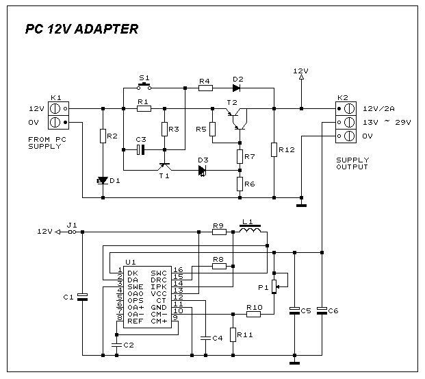
PC 12V ADAPTER
This circuit provides a short circuit protected power supply from PC 12V supply voltage. This is particularly handy when working with PC interfacing projects. More: Fig-1 shows the circuit diagram of the complete power supply. The necessary 12V supply voltage...

Charger for 12V lead acid battery
A battery is a vital element of any battery-backed system. In many cases, the battery is more expensive than the system it is backing up. Hence, practical measures must be adopted to conserve battery life. As per manufacturer's data sheets,...
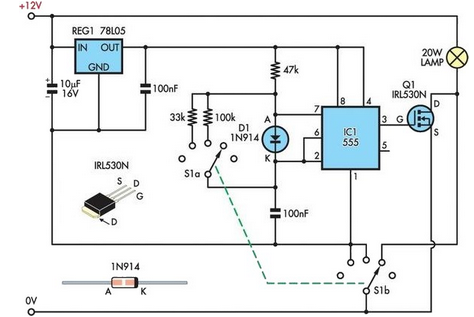
12V Halogen Dimmer
A 12V 20W halogen lamp (MR16) and a 4.2Ah SLA battery are utilized in a bike light system. Due to the limited lifespan of the battery at this power rating, a cost-effective light dimmer was designed to reduce battery consumption...