


Power tool torque control
#torque control
#electric drill
#SCR
#speed control
#motor
#back voltage
#gate voltage
#current control

Description: As the speed of an electric drill decreases due to loading, its torque also diminishes. A compensating speed control circuit restores power to the motor. When the drill slows down, the back voltage developed across the motor—connected in series with the SCR cathode and gate—drops. Consequently, the SCR gate voltage increases relative to the reduced back voltage. This additional gate voltage allows the SCR to conduct over a wider angle, resulting in more current being supplied to the drill, even as its speed declines under load. Additionally, the SCR should be mounted in a block of aluminum or copper that is at least 1 inch square and 0.5 inches thick. For prolonged use of the circuit, a piece measuring 2 inches square is recommended.
The described circuit employs a silicon-controlled rectifier (SCR) to enhance the performance of an electric drill under load conditions. The primary function of the SCR in this application is to regulate the power supplied to the motor as its operational speed decreases. When the drill encounters resistance, such as when drilling into a hard material, the load increases, causing the motor speed to drop. This drop in speed leads to a reduction in back EMF (electromotive force), which is an inherent characteristic of electric motors.
The back EMF serves to oppose the applied voltage and is directly proportional to the motor speed. As the back EMF decreases, the voltage at the SCR gate increases, enabling the SCR to conduct more effectively. This behavior effectively compensates for the loss in torque by allowing a greater amount of current to flow to the motor, thereby maintaining performance despite the increased load.
To ensure optimal thermal management and reliability, it is crucial to mount the SCR on a heat sink made from a thermally conductive material such as aluminum or copper. The recommended dimensions of at least 1 inch square by 0.5 inches thick provide sufficient surface area for heat dissipation during operation. For applications requiring extended use, increasing the size of the heat sink to 2 inches square will further enhance heat management, preventing overheating and ensuring the longevity of the SCR and the overall circuit.
This configuration not only improves the efficiency of the electric drill under load but also contributes to the stability of the operation by maintaining a consistent power output, thereby enhancing the user experience and extending the tool's operational lifespan.As the speed of an electric drill is decreased by loading, its torque also drops. A compensating speed control like this one puts the oomph back into the motor. When the drill slows down, a back voltage developed across the motor—in series with the SCR cathode and gate—decreases. The SCR gate voltage therefore increases relatively as the back voltage is reduced. The extra gate voltage causes the SCR to conduct over a larger angle and more current is driven into the drill, even as speed falls under load
The SCR should be mounted in Vi-in. thick block of aluminum or copper at least 1-in. square. If the circuit is used for extended periods use a 2 inch square piece.
The described circuit employs a silicon-controlled rectifier (SCR) to enhance the performance of an electric drill under load conditions. The primary function of the SCR in this application is to regulate the power supplied to the motor as its operational speed decreases. When the drill encounters resistance, such as when drilling into a hard material, the load increases, causing the motor speed to drop. This drop in speed leads to a reduction in back EMF (electromotive force), which is an inherent characteristic of electric motors.
The back EMF serves to oppose the applied voltage and is directly proportional to the motor speed. As the back EMF decreases, the voltage at the SCR gate increases, enabling the SCR to conduct more effectively. This behavior effectively compensates for the loss in torque by allowing a greater amount of current to flow to the motor, thereby maintaining performance despite the increased load.
To ensure optimal thermal management and reliability, it is crucial to mount the SCR on a heat sink made from a thermally conductive material such as aluminum or copper. The recommended dimensions of at least 1 inch square by 0.5 inches thick provide sufficient surface area for heat dissipation during operation. For applications requiring extended use, increasing the size of the heat sink to 2 inches square will further enhance heat management, preventing overheating and ensuring the longevity of the SCR and the overall circuit.
This configuration not only improves the efficiency of the electric drill under load but also contributes to the stability of the operation by maintaining a consistent power output, thereby enhancing the user experience and extending the tool's operational lifespan.As the speed of an electric drill is decreased by loading, its torque also drops. A compensating speed control like this one puts the oomph back into the motor. When the drill slows down, a back voltage developed across the motor—in series with the SCR cathode and gate—decreases. The SCR gate voltage therefore increases relatively as the back voltage is reduced. The extra gate voltage causes the SCR to conduct over a larger angle and more current is driven into the drill, even as speed falls under load
The SCR should be mounted in Vi-in. thick block of aluminum or copper at least 1-in. square. If the circuit is used for extended periods use a 2 inch square piece.

SCR to make a small solid state tesla coil
An SCR (Silicon Controlled Rectifier) functions similarly to a diode, allowing current to flow in one direction and can be turned on; it remains in this state until the power is interrupted. The query arises regarding its application in circuits,...

It can send a signal to start forward rotation start circuit
The circuit shown in Figure 3-21 is designed to produce a motor startup sound and a light signal indicating the completion of the startup process, after which the signal ceases. This circuit is tailored to control the motor for a...

Code-practice-oscillator
Capacitor C1 charges through resistor R1, and when the gate level established by potentiometer R2 is sufficiently high, the SCR is triggered. Current flows through the SCR and earphones, discharging C1. The anode voltage and current drop to a low...

Circuit forms constant-current SCR
A typical silicon-controlled rectifier (SCR) requires a trigger current to latch on. Once the device is latched, the current flowing through the SCR is determined only by the external component values. The SCR lacks the ability to limit current flow...

Forward and reverse speed control circuit can be integrated with a brake function
Figure 3173 illustrates a control circuit for a wound rotor induction motor that enables mechanical braking, dynamic braking, and reverse braking functions. The circuit includes various components such as relays, contactors, and time relays to manage the motor's speed in...

The integrated three pulse trigger components KCZ3 electrical schematic
The KCZ3 is an integrated three-pulse triggering component designed for use in three-phase half-bridge inverters. Each phase output pulse can reliably drive a high-power thyristor and is adaptable to various phase voltages. The electrical parameters are as follows: Phase shift...

Auto Ignition Cut-Off
This circuit utilizes a combination of a silicon-controlled rectifier (SCR) and a relay to interrupt the ignition system unless a positive voltage is applied to the gate of the SCR. This configuration serves as an anti-theft device, as the vehicle...

Switching two-speed motor control circuit
The motor switch control circuit depicted in the figure provides two speed settings for counter-steering, allowing for operation at two speeds in opposite directions.
The motor switch control circuit is designed to facilitate the operation of a motor at two distinct...
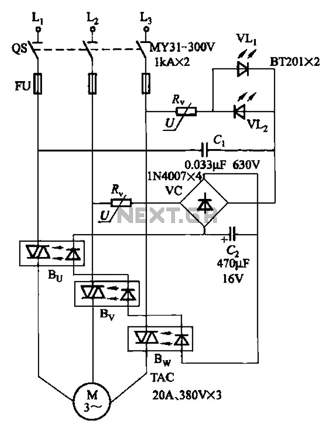
Three-way operation allows the motor-controlled circuits
The circuit depicted in Figure 3-93 is integrated with an optical phase sequence protection relay.
The circuit in question is designed to provide phase sequence protection using an optical relay mechanism. Optical phase sequence protection relays are crucial in applications where...