


Servomotor-based mobile robot control
#servomotor
#mobile robot
#Boe Bot
#Basic Stamp
#robotics
#industrial applications
#hobby projects
#Parallax
#motor driver
#automation

Description: Mobile robots are utilized in various industrial, commercial, research, and hobby applications. This project focuses on controlling a mobile robot using servomotors. The robot is based on a well-known mobile robot called Boe Bot, developed by Parallax. The basic robot is controlled by a Basic Stamp controller (a trademark of Parallax Inc.). The author has modified the robot base and electronic circuit to enable compatibility with PIC microcontrollers. The robot features two side drive wheels and a caster wheel at the rear. Each drive wheel is linked to a servomotor. A breadboard is mounted on the robot base to accommodate the electronic control circuit. The robot is powered by a 9V battery, with a 78L05 voltage regulator employed to provide a stable 5V supply for the microcontroller circuit. Programs have been developed to enable the robot to move forward, backward, and turn left and right. The circuit diagram for this project is illustrated in the accompanying figure. A PIC16F84 microcontroller is utilized, operating with a 4 MHz crystal.
The servomotors are modified for continuous rotation in either direction through pulse application. Typically, a pulse width of 1.3 ms causes the motor to rotate clockwise at full speed, while a pulse width of 1.7 ms rotates it counterclockwise, and a pulse width of 1.5 ms stops the motor. Typical pulse widths required to drive modified servomotors are shown in the figure. The pulse for operating a servomotor can be easily generated using the PULSOUT statement in the PicBasic and PicBasic Pro compilers. With a 4 MHz crystal, the PULSOUT timing is measured in 10 µs increments. For example, a PicBasic statement can generate a pulse width of 1.3 ms from bit 0 of PortB, as 1.3 ms equals 1300 µs, which translates to 130 when divided by 10. The left servomotor is connected to bit 0 of PORTB (RB0), while the right servomotor is connected to bit 1 of PORTB (RB1). While some servomotors can operate at a 5V supply, most require between 6 to 9V. The delay between pulses determines motor speed, with a common value of around 20 ms. The following PicBasic code demonstrates how to control a servomotor connected to port RB0.
In this mobile robot control application, the integration of the PIC16F84 microcontroller provides a robust platform for managing the servomotor operations and overall functionality of the robot. The utilization of modified servomotors allows for precise control over the robot's movement, enabling it to navigate various environments effectively. The implementation of a 78L05 voltage regulator ensures that the microcontroller receives a consistent power supply, which is critical for reliable operation. The choice of a breadboard for the electronic control circuit facilitates easy modifications and testing during the development phase.
The programming aspect of the project leverages the capabilities of the PicBasic and PicBasic Pro compilers, allowing for straightforward control commands to be issued to the servomotors. The timing of the pulse outputs is crucial, as it directly affects the speed and direction of the robot's movement. The use of specific pulse widths for clockwise, counterclockwise, and stop commands ensures that the robot can be accurately maneuvered in various directions, enhancing its operational versatility.
In summary, this project exemplifies the application of servomotor technology in mobile robotics, highlighting the importance of microcontroller integration, power regulation, and precise programming in achieving effective control of robotic systems. The design and implementation considerations discussed provide a foundational understanding for further exploration and development in the field of mobile robotics.Mobile robots are used in many industrial, commercial, research, and hobby applications. This project is about the control of a mobile robot using servomotors. The robot used in this project is the base of a popular mobile robot known as Boe Bot, developed by Parallax ( and The basic robot is controlled from a Basic Stamp controller (Trademark of Parallax Inc. ). The robot base and electronic circuit have been modified by the author so that the robot can be used with PIC microcontrollers ( Figure 1). The robot consists of two side drive wheels and a caster wheel at the back. The drive wheels are connected to servomotors. A breadboard is placed on the robot base for the electronic control circuit. The robot is driven from a 9V battery, and a 78L05-type voltage regulator is used to obtain _5V to supply power to the microcontroller circuit.
In this project programs are developed to move the robot forward, backward, and to turn left and right. The circuit diagram of the project is shown in Figure 2. In this project a PIC16F84 microcontroller is used and the microcontroller is operated with a 4 MHz crystal.
Operating the servomotor As described in Section 4. 7 the servomotors used in robotic applications are modified servos where the motor can rotate in either direction continuously by applying pulses to the servomotor. In a modified servomotor typically a pulse with a width of 1. 3 ms rotates the motor clockwise at full speed. A pulse with a width of 1. 7 ms rotates the motor anti-clockwise, and a pulse with a width of 1. 5 ms stops the motor. Figure 3 shows typical pulses used to drive modified servomotors. The pulse required to operate a servomotor can very easily be obtained using the PULSOUT statement of the PicBasic and PicBasic Pro compilers.
When a 4 MHz crystal is used, the time interval of PULSOUT is in units of 10_s. For example, the following PicBasic statement generates a pulse with a width of 1. 3 ms from bit 0 of PortB (1. 3 ms _ 1300_s and 1300/10 _ 130): Servomotors are used to drive the left wheel and the right wheel. A servomotor has three leads: power supply, ground, and the signal pin. Left servomotor is connected to bit 0 of PORTB (RB0), and right servomotor is connected to bit 1 of PORTB (RB1). Although some servomotors can operate with _5V supply, most servomotors require 6 9V to operate. Similarly, the following PicBasic statement generates a pulse with a width of 1. 7 ms from bit 1 of PORTB: delay determines the speed of the motor and about 20 ms is most commonly used value.
The following PicBasic (or PicBasic Pro) code shows how a servomotor connected to port RB0
The servomotors are modified for continuous rotation in either direction through pulse application. Typically, a pulse width of 1.3 ms causes the motor to rotate clockwise at full speed, while a pulse width of 1.7 ms rotates it counterclockwise, and a pulse width of 1.5 ms stops the motor. Typical pulse widths required to drive modified servomotors are shown in the figure. The pulse for operating a servomotor can be easily generated using the PULSOUT statement in the PicBasic and PicBasic Pro compilers. With a 4 MHz crystal, the PULSOUT timing is measured in 10 µs increments. For example, a PicBasic statement can generate a pulse width of 1.3 ms from bit 0 of PortB, as 1.3 ms equals 1300 µs, which translates to 130 when divided by 10. The left servomotor is connected to bit 0 of PORTB (RB0), while the right servomotor is connected to bit 1 of PORTB (RB1). While some servomotors can operate at a 5V supply, most require between 6 to 9V. The delay between pulses determines motor speed, with a common value of around 20 ms. The following PicBasic code demonstrates how to control a servomotor connected to port RB0.
In this mobile robot control application, the integration of the PIC16F84 microcontroller provides a robust platform for managing the servomotor operations and overall functionality of the robot. The utilization of modified servomotors allows for precise control over the robot's movement, enabling it to navigate various environments effectively. The implementation of a 78L05 voltage regulator ensures that the microcontroller receives a consistent power supply, which is critical for reliable operation. The choice of a breadboard for the electronic control circuit facilitates easy modifications and testing during the development phase.
The programming aspect of the project leverages the capabilities of the PicBasic and PicBasic Pro compilers, allowing for straightforward control commands to be issued to the servomotors. The timing of the pulse outputs is crucial, as it directly affects the speed and direction of the robot's movement. The use of specific pulse widths for clockwise, counterclockwise, and stop commands ensures that the robot can be accurately maneuvered in various directions, enhancing its operational versatility.
In summary, this project exemplifies the application of servomotor technology in mobile robotics, highlighting the importance of microcontroller integration, power regulation, and precise programming in achieving effective control of robotic systems. The design and implementation considerations discussed provide a foundational understanding for further exploration and development in the field of mobile robotics.Mobile robots are used in many industrial, commercial, research, and hobby applications. This project is about the control of a mobile robot using servomotors. The robot used in this project is the base of a popular mobile robot known as Boe Bot, developed by Parallax ( and The basic robot is controlled from a Basic Stamp controller (Trademark of Parallax Inc. ). The robot base and electronic circuit have been modified by the author so that the robot can be used with PIC microcontrollers ( Figure 1). The robot consists of two side drive wheels and a caster wheel at the back. The drive wheels are connected to servomotors. A breadboard is placed on the robot base for the electronic control circuit. The robot is driven from a 9V battery, and a 78L05-type voltage regulator is used to obtain _5V to supply power to the microcontroller circuit.
In this project programs are developed to move the robot forward, backward, and to turn left and right. The circuit diagram of the project is shown in Figure 2. In this project a PIC16F84 microcontroller is used and the microcontroller is operated with a 4 MHz crystal.
Operating the servomotor As described in Section 4. 7 the servomotors used in robotic applications are modified servos where the motor can rotate in either direction continuously by applying pulses to the servomotor. In a modified servomotor typically a pulse with a width of 1. 3 ms rotates the motor clockwise at full speed. A pulse with a width of 1. 7 ms rotates the motor anti-clockwise, and a pulse with a width of 1. 5 ms stops the motor. Figure 3 shows typical pulses used to drive modified servomotors. The pulse required to operate a servomotor can very easily be obtained using the PULSOUT statement of the PicBasic and PicBasic Pro compilers.
When a 4 MHz crystal is used, the time interval of PULSOUT is in units of 10_s. For example, the following PicBasic statement generates a pulse with a width of 1. 3 ms from bit 0 of PortB (1. 3 ms _ 1300_s and 1300/10 _ 130): Servomotors are used to drive the left wheel and the right wheel. A servomotor has three leads: power supply, ground, and the signal pin. Left servomotor is connected to bit 0 of PORTB (RB0), and right servomotor is connected to bit 1 of PORTB (RB1). Although some servomotors can operate with _5V supply, most servomotors require 6 9V to operate. Similarly, the following PicBasic statement generates a pulse with a width of 1. 7 ms from bit 1 of PORTB: delay determines the speed of the motor and about 20 ms is most commonly used value.
The following PicBasic (or PicBasic Pro) code shows how a servomotor connected to port RB0

Constant-speed-motor-driver
When the torque load on the motor increases, its current also rises. This increase in current is detected across Rs, and positive feedback is applied to the noninverting terminal of the LH0101, which in turn raises the motor voltage to...

Big Trak Motor Driver Schematic
Schematic of Big Trak's motor driver circuit. The toy includes 9112 and 9113 transistors (and sometimes 2N6715) because the 75494 chip cannot supply enough current to run the Big Trak's motors by itself.
The motor driver circuit for the Big Trak...
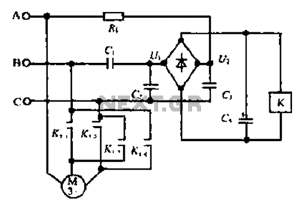
A motor reversing automatic adjustment circuit
Composition ratio circuit. The circuit consists of resistors and capacitors that form a shift register circuit with diodes VD1 to VD4, creating a bridge for electric current. Capacitor C4 is utilized for filtering applications and for eliminating instantaneous relay energization...
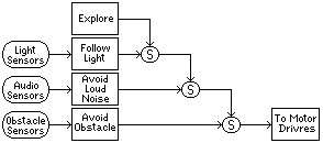
Subsumption Architecture
This term refers to a robotic control concept developed by Rodney Brooks, closely associated with behavior-based robotics, which incorporates modular behavior-based artificial intelligence. Unlike traditional artificial intelligence that relies on a centralized, top-down planning, execution, and monitoring structure, subsumption architecture...

mobile robot schematics
Mobile robot schematic diagram for a cellphone-controlled robot. Detailed modules used for the cellphone-controlled mobile robot include: DTMF Decoder: MT8870/CM8870; Microcontroller: ATMEGA16; Motor Driver: L293D; Actuator: DC Motor 5-6V.
The mobile robot schematic diagram is designed for operation via a cellphone...

Coop automatic controller circuit diagram
The automatic controller for a chicken coop is designed to automatically regulate light, temperature, and humidity, thereby enhancing egg production and survival rates of chickens. This device is intended for specialized poultry households in rural areas. The circuit operates through...
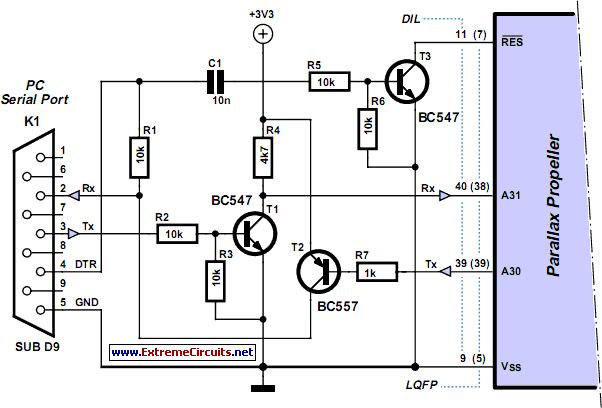
programming propeller ic
Parallax, known for its successful Basic Stamp integrated circuit (IC), has recently launched the Propeller: a new microcontroller that features a unique design. It incorporates eight 32-bit processors, referred to as COGs in Propeller terminology, within a single 40-pin package....

Custom Motor Driver
This chapter was removed from Applied Robotics 2 due to space constraints. It addresses general motor control issues and details the construction of a 5-amp motor driver. The principles discussed can be applied to larger motor controllers. Although commercially available...

Robotics Page
This is an attempt to create a simple and compact photovore. Although it may not be visually appealing, it serves as a good starting point for beginners. It is a personal version of the Dozer photovore. The latest robot built...