


SG3525 PWM DC Motor Circuit
#SG3525
#PWM
#DC motor
#voltage conversion
#pulse duration
#motor driver
#speed control
#H-bridge
#power electronics
#control circuit
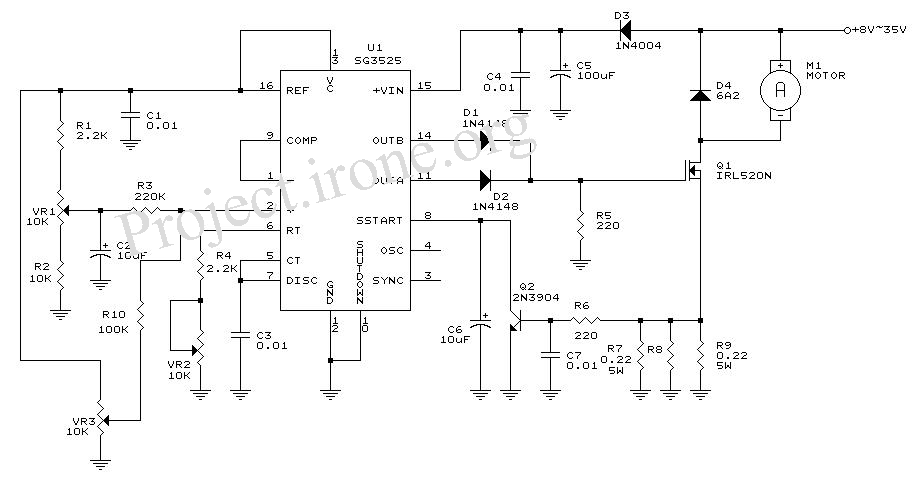
Description: The circuit diagram is designed for precise control of DC motors. It converts DC voltage into a series of pulses, where the duration of each pulse...
The circuit utilizes a pulse-width modulation (PWM) technique to regulate the speed and torque of DC motors. The fundamental principle behind PWM is the adjustment of the duty cycle of the voltage applied to the motor. By varying the width of the pulses, the average voltage and current supplied to the motor can be effectively controlled, allowing for smooth operation and enhanced efficiency.
Key components of the circuit include a microcontroller or a PWM generator, a power transistor or MOSFET, and the DC motor itself. The microcontroller generates a PWM signal, which is then fed into the gate of the power transistor. When the PWM signal is high, the transistor conducts, allowing current to flow to the motor. Conversely, when the PWM signal is low, the transistor turns off, interrupting the current flow.
To ensure accurate control, the circuit may include feedback mechanisms, such as encoders or tachometers, which monitor the motor's speed and position. This feedback is processed by the microcontroller to adjust the PWM signal dynamically, maintaining the desired performance parameters.
Additional components such as diodes may be included for flyback protection, safeguarding the circuit from voltage spikes generated by the inductive load of the motor. Capacitors might also be employed to smooth out the voltage supply and reduce electrical noise, further enhancing the stability of the control system.
Overall, this circuit diagram is an effective solution for achieving precise and efficient control of DC motors in various applications, including robotics, conveyor systems, and automotive systems.The Circuit diagram is ideal for accurate control of DC motors. DC voltage conversion to a series of pulses, such that the duration of the pulse ..
The circuit utilizes a pulse-width modulation (PWM) technique to regulate the speed and torque of DC motors. The fundamental principle behind PWM is the adjustment of the duty cycle of the voltage applied to the motor. By varying the width of the pulses, the average voltage and current supplied to the motor can be effectively controlled, allowing for smooth operation and enhanced efficiency.
Key components of the circuit include a microcontroller or a PWM generator, a power transistor or MOSFET, and the DC motor itself. The microcontroller generates a PWM signal, which is then fed into the gate of the power transistor. When the PWM signal is high, the transistor conducts, allowing current to flow to the motor. Conversely, when the PWM signal is low, the transistor turns off, interrupting the current flow.
To ensure accurate control, the circuit may include feedback mechanisms, such as encoders or tachometers, which monitor the motor's speed and position. This feedback is processed by the microcontroller to adjust the PWM signal dynamically, maintaining the desired performance parameters.
Additional components such as diodes may be included for flyback protection, safeguarding the circuit from voltage spikes generated by the inductive load of the motor. Capacitors might also be employed to smooth out the voltage supply and reduce electrical noise, further enhancing the stability of the control system.
Overall, this circuit diagram is an effective solution for achieving precise and efficient control of DC motors in various applications, including robotics, conveyor systems, and automotive systems.The Circuit diagram is ideal for accurate control of DC motors. DC voltage conversion to a series of pulses, such that the duration of the pulse ..

Wilf Rigter`s reversing H-bridge
This H-bridge variant was one of the first in which the reversing circuitry is built into the driver, rather than (as is more-commonly done) into the control circuitry upstream of the driver. This is a handy circuit, though, for 2-motor...

PWM Motor Speed Controller
A pulse width modulator (PWM) is a device that may be used as an efficient light dimmer or DC motor speed controller. The circuit described here is for a general purpose device that can control DC devices which draw up...

Motor control diy
The motor is rated at 6W, which corresponds to a current of 0.5 amps at a voltage of 12V. It is recommended to use a 12V DC power supply with a rating of 1A or higher. Any type of power...

STALLED_MOTOR_PROTECTION
The modification of a basic speed control circuit for small DC permanent-magnet motors implements a maximum current limit during normal operating conditions and a reduced current limit during stall conditions. This design aims to limit the dissipation of series transistor...
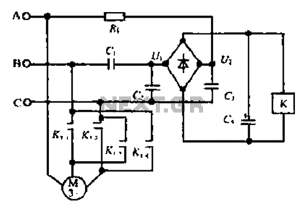
A motor reversing automatic adjustment circuit
Composition ratio circuit. The circuit consists of resistors and capacitors that form a shift register circuit with diodes VD1 to VD4, creating a bridge for electric current. Capacitor C4 is utilized for filtering applications and for eliminating instantaneous relay energization...

current simple h-bridge polarity reversal
Construct an H-bridge specifically for reversing current, as speed control is managed separately. Is it feasible to connect two N-channel MOSFETs and two P-channel MOSFETs to an IO pin from the microcontroller (with appropriate resistors), or is the process more...
STALLED_MOTOR_PROTECTION
The modification of a basic speed control circuit for small DC permanent-magnet motors implements a maximum current limit during normal operating conditions and a reduced current limit during stall conditions. This design aims to limit the dissipation of series transistor...

6-transistor H-bridge
Mark Tilden's 6-transistor H-bridge Design, limitations, usage
This is the six transistor "Tilden style" H-bridge; while not as old as the original "basic H-bridge," this goes "way back," and is the basis for many BEAM driver circuits.
* Up to 800 mA...
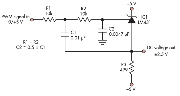
Digitally adjustable precision reference driven via PWM
This simple circuit converts a 5V PWM signal into a variable precision reference voltage with a range of -2.5V to +2.5V. Many designs, such as a digitally controlled power supply or a programmable dummy load, require a Digital to Analog...