


Since a power charger circuit
#bidirectional control
#motor driver
#power charger
#voltage regulator
#switching
#energy
#automotive
#battery charger
#circuit design

Description: Bidirectional control is implemented for a motor to increase its operational degree. The motor can rotate in either direction with a current of 1A. A variable duty cycle multivibrator is utilized to achieve the construction and control of the motor's direction. The system includes a potentiometer that, when adjusted, alters the oscillation waveform symmetry. When the motor is halted, sliding the potentiometer to one side will cause the motor to rotate in the corresponding direction.
A schematic for a bidirectional motor control circuit typically includes several key components: a multivibrator circuit, a motor driver, and a potentiometer for user input. The multivibrator generates a pulse-width modulation (PWM) signal, which is essential for controlling the speed and direction of the motor. The duty cycle of this PWM signal can be varied by adjusting the potentiometer, allowing for fine-tuned control over the motor's operation.
The motor driver, often implemented using an H-bridge configuration, enables the motor to rotate in both directions. The H-bridge consists of four switches (transistors or MOSFETs) that can be activated in pairs to reverse the polarity of the voltage applied to the motor. This arrangement allows the motor to be driven forward or backward by changing the state of the switches based on the PWM signal from the multivibrator.
In the circuit, when the potentiometer is centered, the multivibrator produces a symmetrical waveform, resulting in no net movement of the motor. Adjusting the potentiometer to one side increases the duty cycle of the PWM signal, which in turn increases the average voltage supplied to the motor, causing it to rotate in one direction. Conversely, moving the potentiometer to the opposite side decreases the duty cycle, reversing the motor's rotation.
The inclusion of feedback mechanisms, such as limit switches or encoders, can enhance the functionality of this circuit by providing position feedback to the control system, allowing for precise control of the motor's movement. Overall, this bidirectional control circuit is a versatile solution for applications requiring adjustable motor speed and direction. Bidirectional Control J 7 cases referred to the motor is to increase the degree I had a bit-what is to be achieved. iL Sweet Road 1-62 Figure 1 shows, the motor monkeys move J discernible star only 1.29310. It may be in either direction of the Zhu Bu j current 1A. The use of a variable duty cycle of the multivibrator that jil realization of construction and control direction. Located in the heart of towel when the potential of clamor, the oscillation waveform symmetry, when the motor is stopped when the potentiometer slide to one side.
Will be in the direction corresponding to the given partial giant, the motor is rotated.
A schematic for a bidirectional motor control circuit typically includes several key components: a multivibrator circuit, a motor driver, and a potentiometer for user input. The multivibrator generates a pulse-width modulation (PWM) signal, which is essential for controlling the speed and direction of the motor. The duty cycle of this PWM signal can be varied by adjusting the potentiometer, allowing for fine-tuned control over the motor's operation.
The motor driver, often implemented using an H-bridge configuration, enables the motor to rotate in both directions. The H-bridge consists of four switches (transistors or MOSFETs) that can be activated in pairs to reverse the polarity of the voltage applied to the motor. This arrangement allows the motor to be driven forward or backward by changing the state of the switches based on the PWM signal from the multivibrator.
In the circuit, when the potentiometer is centered, the multivibrator produces a symmetrical waveform, resulting in no net movement of the motor. Adjusting the potentiometer to one side increases the duty cycle of the PWM signal, which in turn increases the average voltage supplied to the motor, causing it to rotate in one direction. Conversely, moving the potentiometer to the opposite side decreases the duty cycle, reversing the motor's rotation.
The inclusion of feedback mechanisms, such as limit switches or encoders, can enhance the functionality of this circuit by providing position feedback to the control system, allowing for precise control of the motor's movement. Overall, this bidirectional control circuit is a versatile solution for applications requiring adjustable motor speed and direction. Bidirectional Control J 7 cases referred to the motor is to increase the degree I had a bit-what is to be achieved. iL Sweet Road 1-62 Figure 1 shows, the motor monkeys move J discernible star only 1.29310. It may be in either direction of the Zhu Bu j current 1A. The use of a variable duty cycle of the multivibrator that jil realization of construction and control direction. Located in the heart of towel when the potential of clamor, the oscillation waveform symmetry, when the motor is stopped when the potentiometer slide to one side.
Will be in the direction corresponding to the given partial giant, the motor is rotated.

Easy exchange of magnetic saturation voltage regulator circuit
Easy exchange of magnetic saturation voltage regulator circuit
The magnetic saturation voltage regulator circuit is designed to stabilize output voltage levels by utilizing magnetic saturation principles. This circuit typically employs a magnetic core, which operates in saturation to regulate voltage,...

charger for all battery types
Charger for all battery types power supply. This lithium battery charger circuit is dedicated to charging lithium batteries. It uses two chips: the voltage regulator LM317T and ICL7665, which warns microprocessors of overvoltage and undervoltage conditions. Charging is completed with...

SciTech PS-3R Power Supply Circuit
The following circuit illustrates the SciTech PS-3R Power Supply Circuit. Features include 13.8V DC output, 5 Amps surge capability, and a constant output of 3 Amps. Components include a transistor and others.
The SciTech PS-3R Power Supply Circuit is designed to...

5v 1a power supply using lm2575
A power transistor with a voltage drop of 4 volts and a current of 3 amps may dissipate approximately 12 watts of heat, presenting a challenge in series regulators. In contrast, a saturated transistor or MOSFET with a voltage drop...

12 Volt 30 Amp Power Supply
This power supply utilizes a single 7812 integrated circuit (IC) voltage regulator in conjunction with multiple external pass transistors to provide output load currents of up to 30 amps.
The circuit design incorporates a 7812 voltage regulator, which is known for...
MC78L15ABPG Original supply
MC78L15ABPG positive voltage regulator, 100mA, TO-92
The MC78L15ABPG is a low-dropout (LDO) voltage regulator designed to provide a stable output voltage of 15V with a maximum output current of 100mA. This device is packaged in a TO-92 form factor, which is...

18v power supply using lm7818
This power supply operates effectively to provide a stable 18V DC output with a maximum current of 1.5A. The circuit employs an LM7818 positive voltage regulator integrated circuit (IC), which includes several built-in features such as internal current limiting, short...

fixed Current Battery Charger
A simple method of charging a battery from a higher voltage battery is shown in the circuit below to the left. Only one resistor is needed to set the desired charging current and is calculated by dividing the difference in...
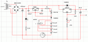
batteries charger and psu circuit
This circuit consists of two main components: a battery charger that provides a fixed output voltage of 5V DC, and a regulated power supply that allows for an adjustable output voltage ranging from 2 to 9 volts.
The circuit design incorporates...