


Stepper motor controller - Driver circuit with circuit design
#stepper motor
#transistor
#driver circuit
#NOT gate
#XOR gate
#motor windings
#control logic
#SL100
#diodes
#circuit design
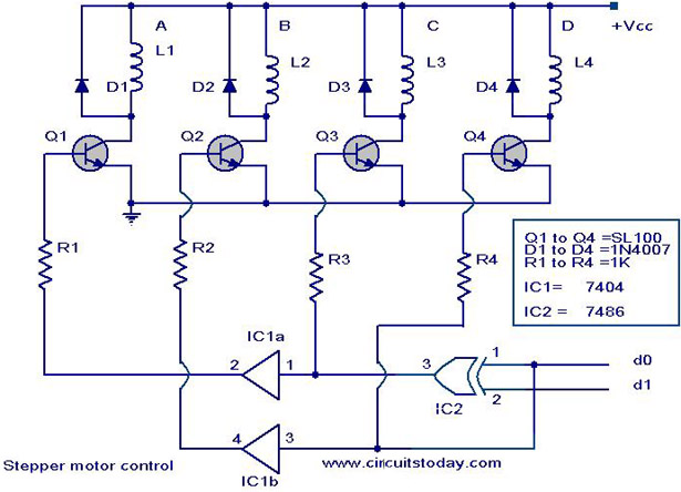
Description: The circuit diagram illustrates a simple stepper motor controller utilizing basic components. The driver circuit employs four SL100 transistors to control the motor windings, along with two NOT gates and one XOR gate to decode the two-bit control logic needed to operate the four windings of the motor. Diodes D1 to D4 safeguard the corresponding transistors from transients generated during the switching of motor windings. The control signals d0 and d1 dictate both the direction of rotation and the speed of the motor. The control logic for this circuit can be derived from a two-bit up/down counter that is clocked by a 555 astable multivibrator. The counting direction determines the rotation direction, while the frequency of the astable multivibrator sets the rotation speed. Vcc represents the voltage required for the stepper motor, which can vary depending on the motor specifications, with a maximum usage of up to 24V for stepper motors. For operations requiring higher voltages and power, the SL100 transistors should be substituted with higher power transistors such as the 2N3055.
The circuit operates by using a four-transistor configuration to sequentially energize the stepper motor windings, allowing for precise control of the motor's position and movement. The transistors function as switches that control the current flow through the motor coils, enabling the motor to step in discrete increments. The NOT gates and XOR gate serve as logic elements that interpret the control signals, ensuring that the correct combination of transistors is activated for the desired stepping sequence.
The 555 timer in astable mode generates a continuous square wave output that acts as a clock signal for the up/down counter. This configuration allows the user to set the desired speed of rotation by adjusting the frequency of the 555 timer, which directly influences the stepping rate of the motor. The up/down counter can be configured to count in either direction, thereby facilitating both clockwise and counterclockwise motor rotation.
The diodes D1 to D4 play a crucial role in protecting the transistors from back EMF generated when the motor windings are switched off. This transient voltage can damage the transistors if not properly managed, making the inclusion of these protective diodes essential for the longevity and reliability of the circuit.
Power supply considerations are also important; the Vcc voltage must be selected based on the specific requirements of the stepper motor being used. While the circuit can accommodate motors rated up to 24V, higher voltage applications necessitate the use of transistors capable of handling the increased power levels, such as the 2N3055, which offers greater current and voltage ratings than the SL100.
Overall, this stepper motor controller circuit is a versatile solution for applications requiring precise motor control, leveraging simple components to achieve effective performance in driving stepper motors.Here is the circuit diagram of a simple stepper motor controller using only elementary parts. The driver circuit uses, four transistor (SL100) to drive the motor windings, two NOT gates and one XOR gate to decode the two bit control logic to drive the four windings of the motor. The diodes D1 to D4 protects the corresponding transistors from trans ients generated during the switching of motor windings. d0 and d1 are the control logics which determines the direction of rotation as well as speed. The control logic for the circuit can be obtained from a 2 bit up/down counter clocked by a 555 astable multivibrator. The direction of count determines the direction of rotation and the frequency of astable multivibrator determines the speed of rotation.
Vcc is the voltage required for the stepper motor. It varies from motor to motor. Here we can use up to 24V stepper motors. For higher operating voltages and power the SL100 transistors must be replaced with higher power transistors like 2N3055.
The circuit operates by using a four-transistor configuration to sequentially energize the stepper motor windings, allowing for precise control of the motor's position and movement. The transistors function as switches that control the current flow through the motor coils, enabling the motor to step in discrete increments. The NOT gates and XOR gate serve as logic elements that interpret the control signals, ensuring that the correct combination of transistors is activated for the desired stepping sequence.
The 555 timer in astable mode generates a continuous square wave output that acts as a clock signal for the up/down counter. This configuration allows the user to set the desired speed of rotation by adjusting the frequency of the 555 timer, which directly influences the stepping rate of the motor. The up/down counter can be configured to count in either direction, thereby facilitating both clockwise and counterclockwise motor rotation.
The diodes D1 to D4 play a crucial role in protecting the transistors from back EMF generated when the motor windings are switched off. This transient voltage can damage the transistors if not properly managed, making the inclusion of these protective diodes essential for the longevity and reliability of the circuit.
Power supply considerations are also important; the Vcc voltage must be selected based on the specific requirements of the stepper motor being used. While the circuit can accommodate motors rated up to 24V, higher voltage applications necessitate the use of transistors capable of handling the increased power levels, such as the 2N3055, which offers greater current and voltage ratings than the SL100.
Overall, this stepper motor controller circuit is a versatile solution for applications requiring precise motor control, leveraging simple components to achieve effective performance in driving stepper motors.Here is the circuit diagram of a simple stepper motor controller using only elementary parts. The driver circuit uses, four transistor (SL100) to drive the motor windings, two NOT gates and one XOR gate to decode the two bit control logic to drive the four windings of the motor. The diodes D1 to D4 protects the corresponding transistors from trans ients generated during the switching of motor windings. d0 and d1 are the control logics which determines the direction of rotation as well as speed. The control logic for the circuit can be obtained from a 2 bit up/down counter clocked by a 555 astable multivibrator. The direction of count determines the direction of rotation and the frequency of astable multivibrator determines the speed of rotation.
Vcc is the voltage required for the stepper motor. It varies from motor to motor. Here we can use up to 24V stepper motors. For higher operating voltages and power the SL100 transistors must be replaced with higher power transistors like 2N3055.

Controlling Stepper Motors Using Power IO Wildcard MOSFET Driver
For optimal efficiency, set MAX_STEPPERS to the number of stepper motors being controlled, with a maximum limit of four. Motors are identified by indices 0, 1, 2, and 3. On the QCard, there is a trade-off between the number of...

micro stepper
In a traditional microstepping motor controller, multiple parallel outputs from a microcontroller are utilized, which are then converted to analog signals using a Digital-to-Analog Converter (DAC) and sent through a power amplifier to drive the motor coils. This method is...
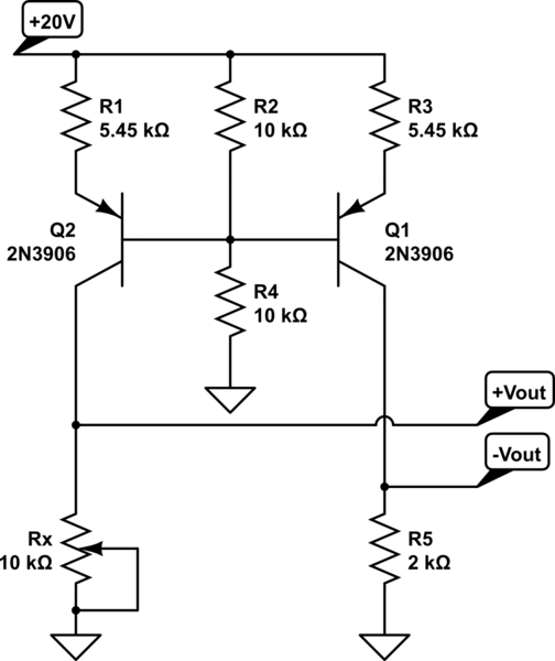
How do you make a shift/scale circuit using a transistor resistors and a voltage source
A functional circuit utilizing an operational amplifier (op-amp); however, the instructor indicated that op-amps can be challenging to work with and provided transistors as an alternative.
Operational amplifiers (op-amps) are versatile components commonly used in various electronic circuits for amplification,...

stepper motor controlling using uln2003
The ULN2003 features high voltage, high current Darlington arrays, each consisting of seven open collector Darlington pairs with common emitters.
The ULN2003 is a versatile integrated circuit designed for driving high-current loads such as relays, motors, and lamps. It operates...
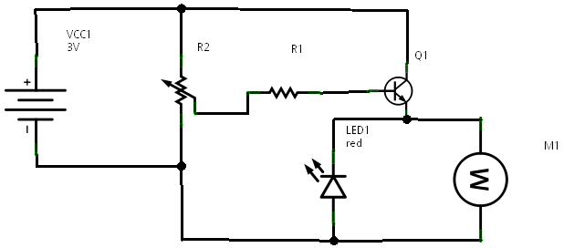
Transistor Current Amplifier Circuit
In a prior post titled "Timing is Everything," the application of PWM (Pulse Width Modulation) signals for controlling devices such as LEDs was discussed. This technique is particularly beneficial when working with digital devices, including microchips and microcontrollers, which often...
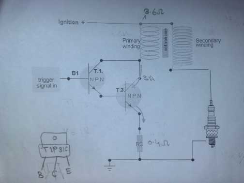
transistor ignition shematic 3
A request for assistance has been made regarding the development of a transistor ignition system to replace the point breaker in a motorcycle. The individual has researched extensively online but has not found a simple and effective circuit. The available...
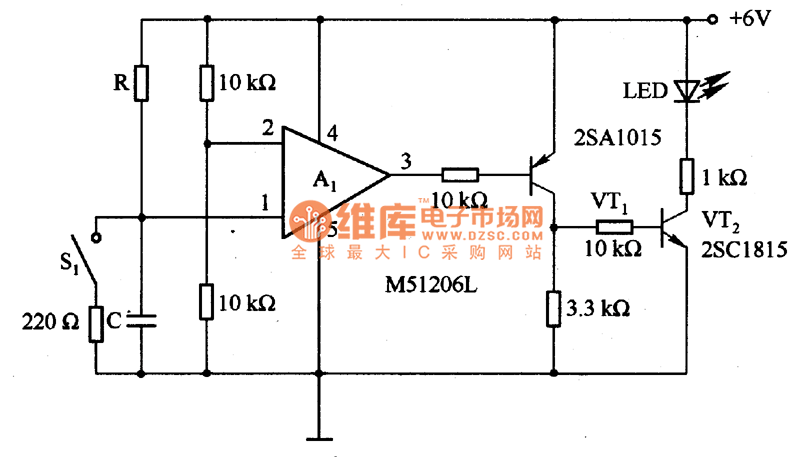
The time delay circuit diagram composed of transistor
The circuit is designed to set a delay time based on the voltage Us and the resistor R. In this configuration, S1 acts as the discharge switch for capacitor C. When switch S1 is closed, the stored charge in capacitor...

Bipolar Transistor HBridge Motor Driver
Schematic, breadboard photo, parts list, and results of several transistor variations on the classic bipolar H-bridge motor driver circuit.
The classic bipolar H-bridge motor driver circuit is a widely used configuration that allows for the control of DC motors in both...

Transistor Mosfet pairs to drive LED cube layers
None of those devices is very suitable. The drivers aren't specified to operate with 3.3V gate signals, and although the typical graph shows that a...
The devices referenced in the original input are not appropriate for the intended application due to...