


Three-phase asynchronous motor PTC protection circuits

Description: A P-type transistor (VT2, VT3) and other components form a common emitter-coupled trigger, functioning as a Schmitt trigger device. This setup serves as a switching circuit to detect changes in the resistance of a PTC thermistor, thereby controlling the action of relay KA. The circuit also includes a transistor (regulator) VTi and additional components that create a simple series regulator, which helps manage supply voltage fluctuations.
The described circuit utilizes P-type transistors VT2 and VT3 configured in a common emitter arrangement, effectively creating a Schmitt trigger that provides hysteresis in the switching action. This characteristic is essential for applications where noise or minor fluctuations in the input signal could lead to undesired switching. The PTC thermistor's resistance change in response to temperature variations is monitored, allowing the circuit to react to specific thermal conditions by activating relay KA.
Relay KA serves as an output device that can control larger loads, making it suitable for applications such as temperature control systems or safety devices. The interaction between the thermistor and the Schmitt trigger ensures that the relay is only activated when the temperature crosses predefined thresholds, thus preventing frequent toggling due to small temperature changes.
Furthermore, the inclusion of the voltage regulator (VTi and associated components) provides stability to the circuit by mitigating supply voltage variations. This regulator is designed as a simple series type, which is effective in maintaining a constant output voltage despite fluctuations in the input supply. The overall design emphasizes robustness and reliability, essential traits for electronic control systems in varying environmental conditions.
The combination of these elements results in a well-rounded circuit capable of precise temperature monitoring and control, with built-in protections against electrical noise and supply voltage instability. By the PI.] P-type transistor VT2, VT3 and other components common emitter-coupled trigger (ie, Schmitt trigger device), equivalent to a switching circuit to detect a change in resistance of the PTC thermistor and the control relay KA action. Figure, by the transistor (regulator) VTi, regulator and other components vs a simple series regulator link for supply voltage fluctuations occasions.
The described circuit utilizes P-type transistors VT2 and VT3 configured in a common emitter arrangement, effectively creating a Schmitt trigger that provides hysteresis in the switching action. This characteristic is essential for applications where noise or minor fluctuations in the input signal could lead to undesired switching. The PTC thermistor's resistance change in response to temperature variations is monitored, allowing the circuit to react to specific thermal conditions by activating relay KA.
Relay KA serves as an output device that can control larger loads, making it suitable for applications such as temperature control systems or safety devices. The interaction between the thermistor and the Schmitt trigger ensures that the relay is only activated when the temperature crosses predefined thresholds, thus preventing frequent toggling due to small temperature changes.
Furthermore, the inclusion of the voltage regulator (VTi and associated components) provides stability to the circuit by mitigating supply voltage variations. This regulator is designed as a simple series type, which is effective in maintaining a constant output voltage despite fluctuations in the input supply. The overall design emphasizes robustness and reliability, essential traits for electronic control systems in varying environmental conditions.
The combination of these elements results in a well-rounded circuit capable of precise temperature monitoring and control, with built-in protections against electrical noise and supply voltage instability. By the PI.] P-type transistor VT2, VT3 and other components common emitter-coupled trigger (ie, Schmitt trigger device), equivalent to a switching circuit to detect a change in resistance of the PTC thermistor and the control relay KA action. Figure, by the transistor (regulator) VTi, regulator and other components vs a simple series regulator link for supply voltage fluctuations occasions.

Alternately flashing lights chain multiple sets of high-power circuit 2
The transistors VTi, VT3, and VTs, along with the RC components, form three distinct multi-resonator oscillators. The oscillation frequency levels are dependent on the values of Ri, R3, Rs, and Cl, as well as Cz and C3s.
The circuit comprises three...
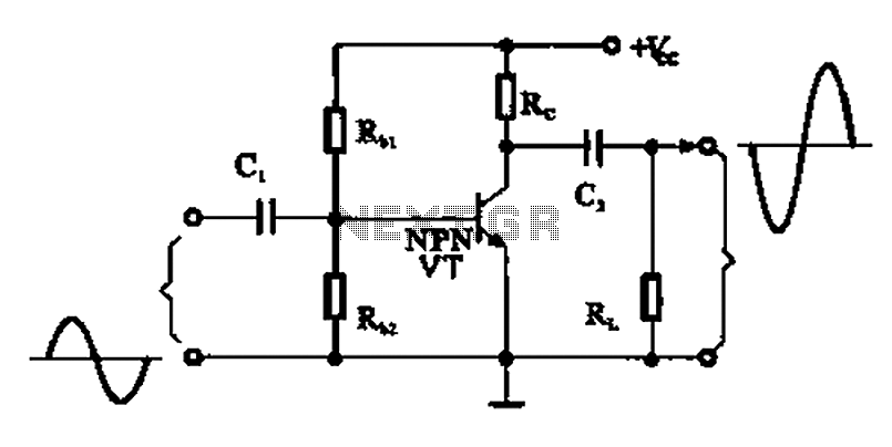
A common emitter amplifier
A common emitter amplifier is a total pole amplification circuit structure featuring a key emitting device. This circuit refers to the emitter of the input signal and the output signal connected to a common ground, forming the basis of fundamental...

Transistorized Auditory Gimmick
This circuit first appeared in "The Braille Technical Press," edited by Robert W. Gunderson, in 1955. Gunderson, W2JIO, designed this "gimmick" to read transmitter meters. It has appeared many times over a 20-year period, including in commercial aids and appliances...
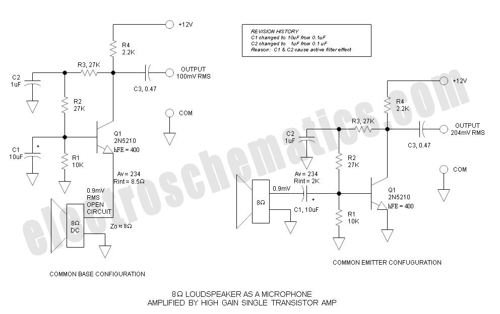
Common Base vs Common Emitter - Single Transistor Amplifier
Single Transistor Amplifier Revisited Part 3, Common Base vs Common Emitter Configuration, Update One nagging question that I have long had is this: How do...
The single transistor amplifier is a fundamental building block in electronic circuits, and its configurations—common base...

lamp flasher circuit
This is a simple two-transistor lamp flasher circuit that can be used to flash a 6-volt lamp. The circuit is compact and can be easily fitted into a small enclosure. It utilizes two transistors: one is an NPN BC549, and...
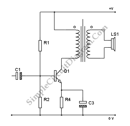
Transistor Class A Power Amplifier
The transistor is biased in Class A, meaning that the collector current flows continuously. This current can vary, increasing or decreasing in response to the input signal.
In a Class A biasing configuration, the transistor operates in the active region for...

Digitally controlled threshold detector
This circuit utilizes small switching transistors, with a maximum motor drive current limited to approximately 250 mA at 5V. Testing has been conducted across a voltage range from 3V to 21V, and with certain component modifications, it may be applicable...

Anti-saturation function delete circuit schematics
Anti-saturation devices have been removed from the UAA4002 routine applications. The base current of the switching transistor, which is driven by another transistor, is automatically adjusted. This adjustment allows the power transistors to operate in critical saturation. However, when the...

Data Switch with LED
Just to prove that transistors can also be useful in logic situations; this is a data latch and indicator which also is a data switch and has a bidirectional input/output port which can be read or switched. If the second...