


Two electric motors or electrical interlocking control circuit
#electric motors
#interlock control
#contactors
#motor driver
#control circuit
#industrial automation
#electrical engineering
#safety interlock

Description: A, B, and two electric motors allow simultaneous operation through interlock control. The two motors can be connected in series with each other using normally closed contacts in the respective coil circuit.
The circuit design facilitates the interlocking operation of two electric motors, referred to as Motor A and Motor B, ensuring that both motors can operate simultaneously without causing electrical faults or mechanical interference. The interlock control system is achieved through the use of normally closed contacts, which are integrated into the coil circuit of each motor.
In this configuration, the normally closed contacts are connected in series with the coils of the motors. When Motor A is energized, the current flows through its coil, causing it to operate. However, the normally closed contact associated with Motor B remains closed, allowing the current to flow to Motor A while preventing Motor B from being activated simultaneously. This arrangement ensures that if one motor is running, the other cannot be activated, thereby preventing potential overload or mechanical failure.
The circuit can be designed using relays or contactors that feature normally closed contacts. Each motor coil is connected to its respective relay, and the relay contacts are wired to form an interlock. This means that when one relay is energized, it opens the circuit for the other relay, effectively preventing both motors from running at the same time.
Additionally, this configuration can be enhanced with safety features such as overload protection and emergency stop buttons. These components can be integrated into the circuit to provide further reliability and safety during operation. The interlock control system is particularly useful in applications where motors must not operate simultaneously due to load constraints or mechanical coupling, ensuring a safe and efficient operational environment.A, B and two electric motors (or electronic) allowed simultaneous operation (interlock control). The two motors can (or electronic) of the respective contact normally closed co ntacts in series with each other interchangeably coil circuit,
The circuit design facilitates the interlocking operation of two electric motors, referred to as Motor A and Motor B, ensuring that both motors can operate simultaneously without causing electrical faults or mechanical interference. The interlock control system is achieved through the use of normally closed contacts, which are integrated into the coil circuit of each motor.
In this configuration, the normally closed contacts are connected in series with the coils of the motors. When Motor A is energized, the current flows through its coil, causing it to operate. However, the normally closed contact associated with Motor B remains closed, allowing the current to flow to Motor A while preventing Motor B from being activated simultaneously. This arrangement ensures that if one motor is running, the other cannot be activated, thereby preventing potential overload or mechanical failure.
The circuit can be designed using relays or contactors that feature normally closed contacts. Each motor coil is connected to its respective relay, and the relay contacts are wired to form an interlock. This means that when one relay is energized, it opens the circuit for the other relay, effectively preventing both motors from running at the same time.
Additionally, this configuration can be enhanced with safety features such as overload protection and emergency stop buttons. These components can be integrated into the circuit to provide further reliability and safety during operation. The interlock control system is particularly useful in applications where motors must not operate simultaneously due to load constraints or mechanical coupling, ensuring a safe and efficient operational environment.A, B and two electric motors (or electronic) allowed simultaneous operation (interlock control). The two motors can (or electronic) of the respective contact normally closed co ntacts in series with each other interchangeably coil circuit,
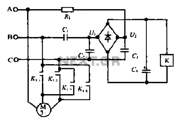
A motor reversing automatic adjustment circuit
Composition ratio circuit. The circuit consists of resistors and capacitors that form a shift register circuit with diodes VD1 to VD4, creating a bridge for electric current. Capacitor C4 is utilized for filtering applications and for eliminating instantaneous relay energization...
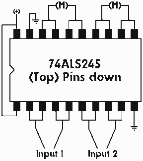
Single IC chip Motor Driver for robots
A motor driver is required in pretty much all walkers including all of my CW series walkers. You need to use it any time you need to supply more current to the motors because the circuit can't supply enough. This...

Constant-speed-motor-driver
When the torque load on the motor increases, its current also rises. This increase in current is detected across Rs, and positive feedback is applied to the noninverting terminal of the LH0101, which in turn raises the motor voltage to...

Big Trak Motor Driver Schematic
Schematic of Big Trak's motor driver circuit. The toy includes 9112 and 9113 transistors (and sometimes 2N6715) because the 75494 chip cannot supply enough current to run the Big Trak's motors by itself.
The motor driver circuit for the Big Trak...

Host stall after stall to auxiliary control circuit
The circuit depicted in Figure 3-84 allows two electric motors to be started independently. The motors can only be activated after pressing the main stop button (SBz) to release contact KMi. Following this, the auxiliary stop button (SB4) can be...

A control circuit reversing braking and reverse grading speed control function
The circuit depicted in Figure 3-168 utilizes a controller for speed grading and reversing control. A reverse brake is connected to the rotor circuit through an overcurrent relay, labeled KI, for control. The current relay KIi to KI3 serves as...

Industrial-Automation
There are three controls that need to be adjusted for a proportional flow controller to function correctly. This process requires practice, and the experience gained can lead to stable control of the flow or velocity of a fluid. The actual...

Music Driven Motor Schematic
Music Driven Motor Schematic. The geared motor drives the stem of a dancing flower to the beat of music.
The music-driven motor schematic involves a geared motor that is activated in response to sound signals, specifically music. This design typically incorporates...

Custom Motor Driver
This chapter was removed from Applied Robotics 2 due to space constraints. It addresses general motor control issues and details the construction of a 5-amp motor driver. The principles discussed can be applied to larger motor controllers. Although commercially available...