


AC bridge using LF356
#LF356
#AC bridge
#impedance matching
#FET input
#resistor matching
#capacitor matching
#op-amp
#differential excitation
#low bias current

Description: The circuit offers a straightforward and economical approach to matching resistors and capacitors. Impedances ZR and Zx create a half-bridge configuration, while OSC and OSC excite the bridge in a differential manner. An external op-amp, specifically a FET input amplifier (LF356), is utilized due to its very low input bias current, typically around 30 pA. Capacitor CI facilitates AC coupling by blocking the DC common mode voltage from the bridge, and resistor Rl serves to bias the output of the LF356 to 0 V at DC. The use of a FET input op-amp ensures that the DC offset caused by the bias current through Rl is minimal. The AC output from the demodulator is filtered using an uncommitted amplifier to generate a DC voltage for the meter. A 10 kΩ potentiometer, R5, limits the current flowing into the meter to a safe level. Calibration starts by applying equal impedances at ZR and Zx, followed by nulling the system offset using the offset adjustment circuit to ensure that Pin 1 reads 0 V. Subsequently, known values are applied at Zx, and meter deviations are calibrated. The bridge is then prepared to measure an unknown impedance at Zx with an accuracy of ±0.05% or better.
The circuit design is based on a half-bridge configuration that effectively balances the impedances ZR and Zx. The differential excitation provided by the OSC signals helps to enhance the sensitivity of the measurement. The LF356 op-amp is chosen for its FET input characteristics, providing high input impedance and low bias currents, which is crucial for accurate impedance matching and measurement, especially in sensitive applications.
Capacitor CI plays a vital role in AC coupling, ensuring that any DC offset present does not interfere with the AC signals being analyzed. This is particularly important in precision measurement applications where the integrity of the AC signal is paramount. Resistor Rl is strategically placed to maintain the output of the LF356 at 0 V under DC conditions, thus preventing any unwanted DC offsets from affecting the measurement accuracy.
The AC output from the demodulator is subjected to filtering through the uncommitted amplifier, which smooths out the signal and converts it into a usable DC voltage for the meter. The inclusion of the 10 kΩ potentiometer (R5) is a safety feature that protects the meter from excessive current, ensuring the longevity and reliability of the measurement system.
Calibration is a critical step in the operation of this circuit. By initially matching impedances at ZR and Zx, the system can be accurately zeroed out, allowing for precise measurements of unknown impedances thereafter. The process of adjusting the offset ensures that the readings are accurate, and the subsequent calibration with known values allows for the fine-tuning of the system to achieve the specified accuracy of ±0.05%.
Overall, this circuit provides a robust solution for impedance measurement, combining cost-effectiveness with high precision, making it suitable for a range of applications in electronics testing and analysis.The circuit provides a simple and cost-effective solution to matching resistors and capacitors. Impedances ZR and Zx form a half-bridge, while OSC and OSC excite the bridge differentially. The external op amp is a FET input amplifier (LF356) with very low input bias current on the order of 30 pA (typical). CI allows ac coupling by blocking the dc common mode voltage from the bridge, while Rl biases the output of LF356 to 0 V at dc.
Use of FET input op amp insures that dc offset due to bias current through Rl is negligible. Ac output of the demodulator is filtered via the uncommitted amp to provide dc voltage for the meter. The 10 k potentiometer, R5, limits the current into the meter to a safe level. Calibration begins by placing equal impedances at ZR and Zx, and the system offset is nulled by the offset adjust circuit so that Pin 1 is at 0 V.
Next, known values are placed at Zx and the meter deviations are calibrated. The bridge is now ready to measure an unknown impedance at Zx with ±0.05% accuracy or better.
The circuit design is based on a half-bridge configuration that effectively balances the impedances ZR and Zx. The differential excitation provided by the OSC signals helps to enhance the sensitivity of the measurement. The LF356 op-amp is chosen for its FET input characteristics, providing high input impedance and low bias currents, which is crucial for accurate impedance matching and measurement, especially in sensitive applications.
Capacitor CI plays a vital role in AC coupling, ensuring that any DC offset present does not interfere with the AC signals being analyzed. This is particularly important in precision measurement applications where the integrity of the AC signal is paramount. Resistor Rl is strategically placed to maintain the output of the LF356 at 0 V under DC conditions, thus preventing any unwanted DC offsets from affecting the measurement accuracy.
The AC output from the demodulator is subjected to filtering through the uncommitted amplifier, which smooths out the signal and converts it into a usable DC voltage for the meter. The inclusion of the 10 kΩ potentiometer (R5) is a safety feature that protects the meter from excessive current, ensuring the longevity and reliability of the measurement system.
Calibration is a critical step in the operation of this circuit. By initially matching impedances at ZR and Zx, the system can be accurately zeroed out, allowing for precise measurements of unknown impedances thereafter. The process of adjusting the offset ensures that the readings are accurate, and the subsequent calibration with known values allows for the fine-tuning of the system to achieve the specified accuracy of ±0.05%.
Overall, this circuit provides a robust solution for impedance measurement, combining cost-effectiveness with high precision, making it suitable for a range of applications in electronics testing and analysis.The circuit provides a simple and cost-effective solution to matching resistors and capacitors. Impedances ZR and Zx form a half-bridge, while OSC and OSC excite the bridge differentially. The external op amp is a FET input amplifier (LF356) with very low input bias current on the order of 30 pA (typical). CI allows ac coupling by blocking the dc common mode voltage from the bridge, while Rl biases the output of LF356 to 0 V at dc.
Use of FET input op amp insures that dc offset due to bias current through Rl is negligible. Ac output of the demodulator is filtered via the uncommitted amp to provide dc voltage for the meter. The 10 k potentiometer, R5, limits the current into the meter to a safe level. Calibration begins by placing equal impedances at ZR and Zx, and the system offset is nulled by the offset adjust circuit so that Pin 1 is at 0 V.
Next, known values are placed at Zx and the meter deviations are calibrated. The bridge is now ready to measure an unknown impedance at Zx with ±0.05% accuracy or better.
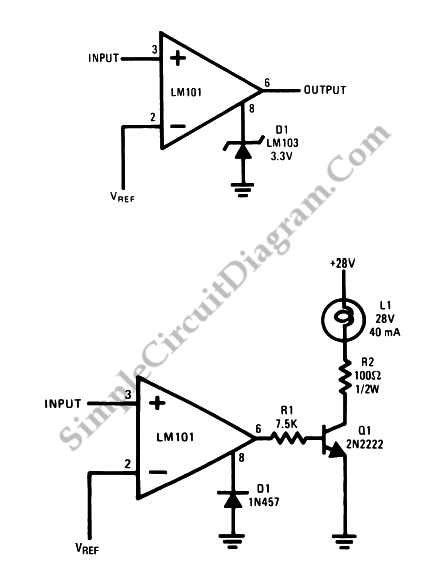
Op-Amp Application: Voltage Comparators
Two reasons why the LM101 is well-suited for comparator applications are its large differential input voltage range and the ease of clamping the output.
The LM101 operational amplifier is particularly advantageous for use in comparator circuits due to its significant differential...

Accurate-variable-gain-circuit
The circuit can utilize any general-purpose, low-offset, low-drift operational amplifier (op amp), such as the OP-07. The differential signal from the bridge feeds into an amplifier that drives a standard, rugged ±50 µA meter. However, near the null point, the...

Triangle / Squarewave Generators
A simple triangle and square wave generator utilizing a common 1458 dual op-amp, capable of operating from very low frequencies up to approximately 10 kHz. The time interval for one half-cycle is determined by the product of resistance (R) and...

Combined Light-/Dark-Activated Switch Circuit
Two operational amplifiers are utilized in a bridge circuit configuration to detect high and low light levels. Potentiometer R2 adjusts the dark level, while resistor R1 controls the light level. Resistor R3 is configured so that approximately 1A of the...

Single op amp oscillator
This circuit incorporates a Schmitt trigger and an integrator configured around a single operational amplifier (op-amp). The timing is regulated by an RC network. The voltage at the inverting input tracks the exponential charging of the capacitor within defined upper...

Square Wave Generator using Op-Amp
Non-sinusoidal waveform generators are also referred to as relaxation oscillators. The op-amp relaxation oscillator depicted in the figure functions as a square wave generator. Generally, square waves are relatively simple to generate. Similar to the UJT relaxation oscillator, the frequency...
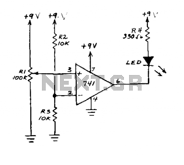
Demo comparator
This circuit is an operational amplifier (op-amp) configuration that operates without a feedback resistor. The junction point of resistors R2 and R3 establishes the reference voltage. When the input voltage, determined by resistor R1, falls below this reference voltage, the...

Filtered-sample-and-hold
It is often necessary to filter a signal prior to sampling. This can be achieved using a single device. Any of the inverting or non-inverting filters that can be constructed with operational amplifiers (op-amps) may be utilized. However, it is...
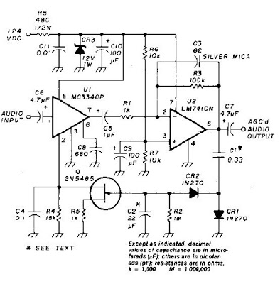
Auto gain Control op-ampCircuit
An audio signal applied to VI is passed through the operational amplifier 741, U2. After being amplified, the output signal V2 is sampled and applied to a negative voltage doubler/rectifier circuit composed of diodes CR1 and CR2, along with capacitor...