


Binary gain step circuit diagram by the PGA205
#PGA205
#gain control
#binary gain
#cascade amplifier
#signal conditioning
#precision amplifier
#instrumentation
#analog circuit
#amplifier

Description: A binary gain step circuit is illustrated using the PGA205, which has a gain range of 1 to 64. The circuit employs two PGA205 devices in cascade, resulting in a total gain that is the product of the individual gains, expressed as G = G1 * G2. The gain settings for each PGA205 are depicted in the accompanying figure.
The binary gain step circuit utilizing the PGA205 operational amplifiers is designed to provide a versatile range of gain settings from 1 to 64, making it suitable for various signal processing applications. The configuration of two PGA205 devices in cascade allows for the multiplication of their individual gains, enhancing the overall gain flexibility of the circuit.
In this circuit, each PGA205 can be independently configured to achieve specific gain values, which are then multiplied together to determine the total gain of the system. This allows for precise control over the amplification process, enabling the circuit to adapt to different input signal levels effectively.
The PGA205 is a programmable gain amplifier that features a range of gain settings that can be controlled digitally. This capability is essential for applications requiring dynamic adjustment of gain in response to varying signal conditions. The gain settings can typically be adjusted through a digital interface, allowing for integration with microcontrollers or digital signal processors (DSPs).
The schematic of the circuit will typically include power supply connections, input and output terminals, and control lines for setting the gain of each PGA205. Capacitive coupling may be employed at the input and output stages to block DC offsets and ensure that only the AC component of the signal is amplified. Additionally, feedback resistors may be used to stabilize the gain and improve linearity across the operational range.
In summary, the binary gain step circuit using two PGA205 amplifiers in cascade configuration provides a robust solution for applications requiring adjustable gain with high precision and flexibility. The design facilitates easy integration into larger systems where gain control is necessary for optimal performance. Binary gain step circuit is shown by PGA205 constituted a gain range of 1 to 64. The circuit uses two PGA205 cascade with a total gain of the circuit is the product of a two-st age gain, that is G G1G2. Each PGA205 gain setting shown in Figure.
The binary gain step circuit utilizing the PGA205 operational amplifiers is designed to provide a versatile range of gain settings from 1 to 64, making it suitable for various signal processing applications. The configuration of two PGA205 devices in cascade allows for the multiplication of their individual gains, enhancing the overall gain flexibility of the circuit.
In this circuit, each PGA205 can be independently configured to achieve specific gain values, which are then multiplied together to determine the total gain of the system. This allows for precise control over the amplification process, enabling the circuit to adapt to different input signal levels effectively.
The PGA205 is a programmable gain amplifier that features a range of gain settings that can be controlled digitally. This capability is essential for applications requiring dynamic adjustment of gain in response to varying signal conditions. The gain settings can typically be adjusted through a digital interface, allowing for integration with microcontrollers or digital signal processors (DSPs).
The schematic of the circuit will typically include power supply connections, input and output terminals, and control lines for setting the gain of each PGA205. Capacitive coupling may be employed at the input and output stages to block DC offsets and ensure that only the AC component of the signal is amplified. Additionally, feedback resistors may be used to stabilize the gain and improve linearity across the operational range.
In summary, the binary gain step circuit using two PGA205 amplifiers in cascade configuration provides a robust solution for applications requiring adjustable gain with high precision and flexibility. The design facilitates easy integration into larger systems where gain control is necessary for optimal performance. Binary gain step circuit is shown by PGA205 constituted a gain range of 1 to 64. The circuit uses two PGA205 cascade with a total gain of the circuit is the product of a two-st age gain, that is G G1G2. Each PGA205 gain setting shown in Figure.

DC-Coupled Audio Amplifier circuit
Designs for audio amplifiers with DC coupling to the load are not frequently seen today, despite offering distinct advantages.
Audio amplifiers that employ DC coupling to the load provide several benefits that can enhance performance in specific applications. In traditional audio...

TS4962 3W Filter-free Class D Audio Power Amplifier With Active Low Standby Mode
Stationary - MOPLL & Silicon Tuner TUA6020 2 Band TV Tuner Mixer-Oscillator-PLL with balanced IF-Amplifier. The TUA6020 device integrates a digitally programmable Phase Locked Loop (PLL) with a mixer-oscillator block that includes two balanced mixers and oscillators suitable for use...

Self Oscillating Amplifier for Distortion Testing
The circuit is based on a simple inductor-capacitor filter circuit, and needs only a pot and a small light bulb to set and stabilise the oscillation. The frequency is fixed, and with a good inductor should be capable of very...

fADC Amplifier Circuit Simulations
A bandwidth-limited amplifier shapes the waveform sampled by the 40 MHz high-speed pipeline Analog to Digital Converter (fast ADC, or fADC). It is well known that the shaping time is twice the time constant (peaking time) for each pole of...

KA9270 Audio Filter Introduction
KGA8010 is a broadband distributed amplifier utilizing 0.1 um-gate GaAs P-HEMT and coplanar waveguide technologies. The KGA8010 can serve as a multi-purpose amplifier for 40 Gb/s optical communication and millimeter wave applications. Manufactured by Oki Semiconductor.
The KGA8010 broadband distributed amplifier...

Amplifiers connecting Bridge
This is a circuit that ensures that you can connect two amplifiers together so you get more power. When called in bridge linking two amplifiers plus you can link the outputs of the amplifiers to the speaker. One of the...

Band decoder circuit diagram
The circuit amplifier and attenuator control video detector consists of a composition for the synchronization channel. The synchronization interval is where the gain circuit is increased.
The described circuit involves an amplifier and an attenuator that work together to control a...

Amplifier Compressor MC3340P
The output is rectified, and TR2 controls the gain of the ICL. This audio compressor circuit uses an MC3340P as a variable gain amplifier.
The audio compressor circuit described utilizes an MC3340P integrated circuit, which functions as a variable gain amplifier...
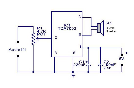
Small or Mini Audio Amplifier Circuit using TDA 7052 IC-Deliver 2 Watts
A compact audio amplifier circuit utilizing the TDA 7052 integrated circuit from Philips. This circuit is suitable for use as a pocket radio amplifier, delivering an output power of 2 watts.
The TDA 7052 is a low-voltage audio amplifier designed specifically...