


Charge amplifier
#charge amplifier
#amplifier
#voltage
#capacitive reactance
#low output impedance
#signal conditioning
#sensor interface
#high impedance input

Description: A charge amplifier is an amplifier whose equivalent input impedance is a capacitive reactance that is very high at low frequencies. Thus, contrary to what its name may suggest, a charge amplifier does not amplify the electric charge present at its input. Its function is actually to obtain a voltage proportional to that charge and yield a low output impedance. Hence, it is a charge-to-voltage converter. Common applications include piezoelectric sensors and photodiodes, in which the charge output from the transducer is converted into a voltage. Charge amplifiers are often found in instrumentation and in the readout circuitry of CCD imagers and flat-panel X-ray detector arrays. In read-out circuits, the objective is usually to measure the very small charge stored within an in-pixel capacitor, despite the capacitance of the circuit track to the readout circuit being a couple of orders of magnitude greater than the in-pixel capacitor. Gain is dependent only on the feedback capacitor, unlike voltage amplifiers, which are affected greatly by the input capacitance of the amplifier and the parallel capacitance of the cable.
Charge amplifiers serve a critical role in converting charge signals from sensors into usable voltage levels, particularly in applications where precision and low noise are paramount. The core operation of a charge amplifier relies on its high input impedance, which minimizes the loading effect on the sensor output. This is particularly important in applications involving piezoelectric sensors, where the generated charge is often very small.
The architecture of a typical charge amplifier includes an operational amplifier (op-amp) configured with a feedback capacitor. The charge from the sensor is fed into the inverting input of the op-amp, while the feedback capacitor is connected between the output and the inverting input. This configuration allows the charge amplifier to produce an output voltage that is directly proportional to the input charge, with the relationship defined by the formula V_out = -Q_in / C_f, where V_out is the output voltage, Q_in is the input charge, and C_f is the feedback capacitance.
In practical applications, charge amplifiers are designed to have low noise characteristics, which is essential for accurate measurements in environments with minimal signal levels. The choice of components, such as the op-amp and feedback capacitor, is crucial in optimizing performance, including bandwidth and stability. Additionally, charge amplifiers are often integrated into more complex systems, such as those used in imaging technologies, where they must accommodate the high capacitance of circuit tracks without compromising the integrity of the signal from the sensor.
Overall, the design and implementation of charge amplifiers are fundamental in fields such as biomedical instrumentation, industrial automation, and scientific research, where the accurate conversion of charge to voltage is essential for data acquisition and analysis.A charge amplifier is an amplifier whose equivalent input impedance is a capacitive reactance that is very high at low frequencies. Thus contrary to what its name may suggest, a charge amplifier does not amplify the electric charge present at its input.
Its function is actually to obtain a voltage proportional to that charge and yield a low output impedance. Hence it is a charge-to-voltage converter. Common applications include piezoelectric sensors and photodiodes, in which the charge output from the transducer is converted into a voltage. Charge amplifiers are often found in instrumentation, and in the readout circuitry of CCD imagers and flat-panel X-ray detector arrays.
In read-out circuits the objective is usually to measure the very small charge stored within an in-pixel capacitor, despite the capacitance of the circuit-track to the readout circuit being a couple of orders of magnitude greater than the in-pixel capacitor. Gain is dependent only on the feedback capacitor, unlike voltage amplifiers, which are affected greatly by the input capacitance of the amplifier and the parallel capacitance of the cable [1] [2]
Charge amplifiers serve a critical role in converting charge signals from sensors into usable voltage levels, particularly in applications where precision and low noise are paramount. The core operation of a charge amplifier relies on its high input impedance, which minimizes the loading effect on the sensor output. This is particularly important in applications involving piezoelectric sensors, where the generated charge is often very small.
The architecture of a typical charge amplifier includes an operational amplifier (op-amp) configured with a feedback capacitor. The charge from the sensor is fed into the inverting input of the op-amp, while the feedback capacitor is connected between the output and the inverting input. This configuration allows the charge amplifier to produce an output voltage that is directly proportional to the input charge, with the relationship defined by the formula V_out = -Q_in / C_f, where V_out is the output voltage, Q_in is the input charge, and C_f is the feedback capacitance.
In practical applications, charge amplifiers are designed to have low noise characteristics, which is essential for accurate measurements in environments with minimal signal levels. The choice of components, such as the op-amp and feedback capacitor, is crucial in optimizing performance, including bandwidth and stability. Additionally, charge amplifiers are often integrated into more complex systems, such as those used in imaging technologies, where they must accommodate the high capacitance of circuit tracks without compromising the integrity of the signal from the sensor.
Overall, the design and implementation of charge amplifiers are fundamental in fields such as biomedical instrumentation, industrial automation, and scientific research, where the accurate conversion of charge to voltage is essential for data acquisition and analysis.A charge amplifier is an amplifier whose equivalent input impedance is a capacitive reactance that is very high at low frequencies. Thus contrary to what its name may suggest, a charge amplifier does not amplify the electric charge present at its input.
Its function is actually to obtain a voltage proportional to that charge and yield a low output impedance. Hence it is a charge-to-voltage converter. Common applications include piezoelectric sensors and photodiodes, in which the charge output from the transducer is converted into a voltage. Charge amplifiers are often found in instrumentation, and in the readout circuitry of CCD imagers and flat-panel X-ray detector arrays.
In read-out circuits the objective is usually to measure the very small charge stored within an in-pixel capacitor, despite the capacitance of the circuit-track to the readout circuit being a couple of orders of magnitude greater than the in-pixel capacitor. Gain is dependent only on the feedback capacitor, unlike voltage amplifiers, which are affected greatly by the input capacitance of the amplifier and the parallel capacitance of the cable [1] [2]

Common intermediate frequency amplifier circuit having a circuit and on the radio
A common intermediate frequency amplifier circuit is presented, along with its components and parameters. The reference values for the components are as follows: 1) Transistors: VT1 to 3DG19, Vcc = 6V. 2) Resistance values: R1 = 50 kΩ, R2 =...
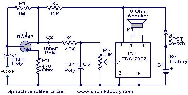
Speech amplifier circuit
This circuit can be housed within a box containing a speaker to create a convenient microphone amplifier. It is suitable for use by teachers, guides, lecturers, and others in crowded or noisy environments. The design is based on the audio...

Marshall JTM-45 and 62 Bluesbreaker Reissue Modifications
The Sovtek 5881 tubes included in these amplifiers are low-quality and produce a corresponding sound. It is advisable to replace all tubes with a Sovtek GZ34, Valve Art or GT KT66 tubes, and Ei Gold preamp tubes. The KT66 tubes...

DC-Coupled Audio Amplifier circuit
Designs for audio amplifiers with DC coupling to the load are not frequently seen today, despite offering distinct advantages.
Audio amplifiers that employ DC coupling to the load provide several benefits that can enhance performance in specific applications. In traditional audio...

USB Powered Audio Power Amplifier
This circuit for multimedia speakers designed for PCs utilizes a single-chip architecture, operates on a low-voltage power supply, is compatible with USB power, facilitates easy heat dissipation, is cost-effective, offers high flexibility, and has a wide temperature tolerance. Central to...

simple-amplifier-with-c945mje340-and.html
This simple amplifier delivers good sound quality with a power output of approximately 10 to 14 Watts and operates on a supply voltage of about 34 to 36 Volts DC. It requires a preamplifier due to its limited advanced features....

audio amp
Install the red LED at D2. Align the flat side of the LED with the PCB outline. Install a jumper wire at R4 and install a 220µF electrolytic capacitor at C8 with the negative side connected to ground. Connect pin...
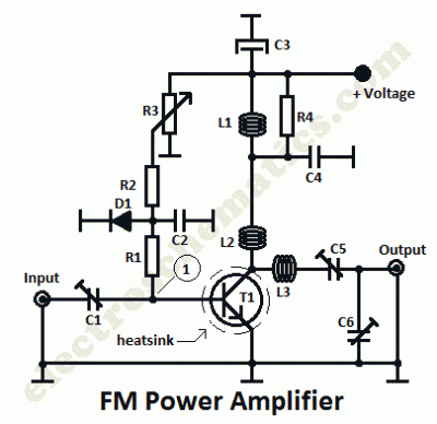
Radio Amplifiers Circuits
This is a 1 watt FM amplifier with a robust design that can be used to amplify an RF signal in the 88 to 108 MHz band. It is highly sensitive when utilizing quality RF power amplifier transistors, trimmers, and...

Power Supply For Amplifiers
For the 60W amplifier, a nominal (full load) supply of +/- 35V is required, so a 25-0-25 secondary is ideal - however, see Updates, below. The circuit for the supply is shown below, and uses separate rectifiers, capacitors and fuses...